2L Opel GT e-boost build

I have a completly different opinion than matnrach. I do believe the flat spot a problem for the heat shrink. Try a test with a shaft with no flat like you said and I think it will be fine. I had the exact same issues when shrink fit on the shaft.
I do think drill and ream is not the solution for concentric hole. Yes you have a precise hole but I believe it’s not the solution for concentric hole. Yes you can slowly increase drill and get a better chance but I don’t beleive to be the best solution.
If you want to make an other test to see what is the best solution, I do believe you should try what I did on mine. Do you remember the procedure I did? Try a smaller fit and glue the shaft instead of shrink fit! Green locktite!
Interesting. Thank you for the thinking and options. I am a novice machinist! I am only just getting my head around dimensions, much less concentricity, cylindrical, and how to measure and achieve them. I only recently bought blue and red loctite. I did not even know that there was a green!

Time for more experiments!
 
If precise shrink fits do not work and create concentricity or other issues then we would not be able to fly anywhere in planes, drive around in cars or do be able to do nearly anything else that involves rotating machinery. Of course it works perfectly well if done properly.
 
If precise shrink fits do not work and create concentricity or other issues then we would not be able to fly anywhere in planes, drive around in cars or do be able to do nearly anything else that involves rotating machinery.
That is NOT the point I mentioned at all. The olny issue in the shrink fit is the flat on the shaft. My first motor was a TP with no flat and the shrink did work fine!
Why I told him to try it with a flat less shaft is to see if his method is correct or not.
If he still have off centric shaft after this means his method lacking somewhere.
Of course it works perfectly well if done properly.
when is done properly, theres no half of the shaft missing
 
So, I cut off my last heat shrink shaft and took a peek inside the motor. does anyone know why there are bearings and brass bushings at each end? I thought it would be one or the other.

There is also a sort of bent spring washer shim, which purpose I am guessing is to take care of end play. I am guessing that is one of my problems (too much end play) given the axial force generated by a cranked up impeller.
 
Last edited:
I honnestly really dont know! I had those in my TP motor too back in the day! Definitely normal but I can’t give you the answer why
 
The brass bushings are to control the end float. When I cut the rotor down I had to make a new one to get the correct end float. Also I deliberately put a very small flat on the end of the shaft to allow the air out as the extension shaft was shrunk on.
 
I think I may have found some other potential contributors to the source of error on my extension shaft run out wonkiness after heat shrinking.
  1. I tried to remove the motor end cap, and it should have slipped right off. But, I was not able to remove it as it got stuck on a burr on the shaft. That same burr could be what made the shaft sit funny.
  2. The flat spot on my shaft is more than a tiny air vent. It is close to 7mm wide across the flat and that is a lot on an 8mm shaft.
  3. The wall thickness on my extension shaft is about 3.8 mm. Might not be that big of a deal if adhesive attached, but might be contributing to excessive force when heat shrinking.

IMG_2447.jpeg
 
I am still trying to reduce runout to 0.001" for a viable extension shaft on my motor. Keep in mind, I am just learning machine work with hobby grade equipment (challenged with set-up, rigidity, quality of tooling, speed limitations, limited torque, etc), but I am an engineer.

I had moved away from turning in my 3 jaw chuck on my lathe to turning between centers for concentricity of this high speed shaft. But upon reflection, I don't think my MT5 dead center is spot on in my spindle, and I don't think that both of the centers that I drilled in my shaft were aligned (cylindrical? concentric) with each other. This would lead to the hole for the shaft not being on the same axis with the 1/4" shaft extension for the compressor wheel, which would generate more runout the longer the shaft is. I have ordered an independent 4 jaw chuck and this should allow me to flip the stock and get it aligned to drill the second center.

In the meantime, back to turning in the 3 jaw chuck…So, upon reflection of the questions posed above by other members, I do believe that my prior 3 jaw procedure had an error. I was drilling the hole for the shaft with the blank deep in the chuck (for more stability), but then extending it out for turning (so was losing my concentricity there, which is now painfully obvious).

Here is my revised 3 jaw chuck procedure to make an extension shaft that I am trying today to do it all in one go to reduce runout.
  1. Cut quality 5/8" steel stock to 4” length on band saw
  2. Ensure lathe tailstock is aligned to spindle
  3. Chuck up stock shallow in 3 jaw chuck, face and chamfer edge
  4. Extend stock in chuck to ensure full shaft length after cut off. Tap in and tighten stock in chuck.
  5. Center drill #4 and enlarge hole taper to 9 mm
  6. Drill 20 mm deep hole using progressive drills: 3/16", 7/32", 1/4", 7.75 mm
  7. Ream to 0.3035” at slow speed
  8. Insert live center to support shaft big end when shaping
  9. Turn down shaft diameter to 8.5 mm leave shoulder at 1”
  10. Turn down for shaft to precisely 0.317” using micrometer for 8 mm bearing Sneak down to it with progressively shallow cuts
  11. Turn compressor shaft to 0.250” using micrometer to measure. Leave 6 mm wide shoulder for bearing
  12. Turn down 0.005" in thread area to about 0.245"
  13. Add chamfers to inside shoulders and polish with 320/400 grit cloth
  14. Remove shaft from lathe, cut off with bandsaw
  15. Chuck big end. Gently face 1/4" shaft end, and chamfer edge
  16. Tap shaft for 1/4" x 20 reverse threads using tail stock tap
I used the above procure, and now my lead hypothesis is that it is a lathe set up issue.
 
Last edited:
  1. Ensure lathe tailstock is aligned to spindle
This can help you to get parallel turning and not be tapered but it’s a waste of time to try to be perfect because every time you tight the tailstock, it will be different every time.
Second, it can help you with your drilling but like I mentioned, the drill and reamer combo is not the best for a concentric hole. BUT there’s probably not your major problem.
  1. Drill 20 mm deep hole using progressive drills: 3/16", 7/32", 1/4", 7.75 mm
I would suggest you to use an Endmill for concentricity. Use a 3/16 drill and 1/4 endmill
  1. Insert live center to support shaft big end when shaping
You can try to machine a nice precision shaft to mount your compressor shaft on, instead of a point. Make it to be able to remove it after all your machinning. But remember, as soon you remove your shaft from the chuck, it will be useless after.


This is the only small change I would do to your procesure.
 
You can try to machine a nice precision shaft to mount your compressor shaft on, instead of a point. Make it to be able to remove it after all your machinning. But remember, as soon you remove your shaft from the chuck, it will be useless after.
Thank you for the input and wisdom WB. I just tried this and it was very slick. I took some 10 mm aluminum stock and turned it down to pop-fit my extension shaft. I just tested the new shaft that I made using the procedure above and it was very clear to see the run-out issue that I had without shrink fitting it to the motor shaft and having to cut it off. I am so happy to have a tool that can help me see what is going on.

Now I need to figure out why my drilled hole is crooked to the OD of the shaft. My lead hypothesis was that there is a lathe set up issue (not properly leveled or tailstock issue). But thanks to you, I have something else to try....
I would suggest you to use an Endmill for concentricity. Use a 3/16 drill and 1/4 endmill
I will try your idea of the 1/4" end mill for concentricity. So, do you just mount the end-mill in the lathe tailstock in a Jacob's chuck or maybe a special collect? and it cuts on the side vs bottom edge and is stiffer that a drill bit?
Thank you for the idea
 
Last edited:
I just tried this and it was very slick.
what do you mean? you try to machined it and it turn itself on the shaft? not sure to understand
not properly leveled or tailstock issue.
you can adjust left to right but usually not up and down. Its one of the reason I don't recommend the tail stock for concentricity. ONLY if you use something more rigid like an endmill
So, do you just mount the end-mill in the lathe tailstock in a Jacob's chuck or maybe a special collect? and it cuts on the side vs bottom edge and is stiffer that a drill bit?
just put it in the chuck like a normal drill! nothing special! you will instantly see if your tail stock suck or not. the endmill is super stiff so even if the tail stock is not leveled or aligned, it will cut straight no matter what. And if its the case. your hole will just be bigger. for example, if your tail is 0.002'' off and you drilled with your 1/4'' endmill, the hole will be 0.254''. instead of a drill of the same diameter, it will never see the 0.002'' of miss aligned.
 
If you are not tired of making new shaft, you can try my technic hahaha!
make all the shaft in a single set-up and keep the hole for the last.
for your second set-up, instead of just flip it in the chuck, make your own ''collet'' in the chuck to grab your part. since is not the most rigid thing is the world, ruff your part first and use the collet to make the finish. again use an endmill or a boring bar to make to hole concentric the the ''collet'' you made and since you are more familiar with the reamer, its ok at this point to use it. I personally bore my hole but there's no big difference at this point since the reamer will flex and follow your concentric hole even if the tail stock is not precise.
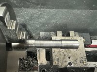
Thanks WB. I just ordered more steel bar stock and plan to make more iterations of the shaft until I have one that is viable, so this is a helpful option to try.

Let me check my understanding
  1. Turn all outer diameter aspects of the extension shaft in one set up held in place between the chuck and a live center in the tailstock?
  2. Create a concentric precision 1/4” hole (collet type item) in a piece of scrap material in the chuck using an end mill for a concentric hole.
  3. Place the 1/4” turned shaft end in the make shift concentric collect and drill the 8mm hole for the motor shaft (again using an end mill or boring bar at some point to ensure concentricity.
 
That’s about right! You can drill smaller but before your reamer you should use an endmill for concentricity
Go check at 7:15
 
I used to ask myself what is wrong with my 7.75 mm drill bit. It was the largest drill before the reamer. The drill ran really funny and made weird noises. I thought it was a bad drill. But, the 7.75 mm drill cut like a dream after the 1/4” end mill got things cylindrical. So I think you were correct an issue with the hole getting off axis.

I also rough leveled my lathe to try to remove some twist from the ways.

I did try the method where the collet is made to hold the shaft to drill the last hole, but I could not make the collet properly. It was helpful to watch your video and see how you made the temporary collet.
 
Last edited:
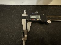
I just got a digital micrometer! So I measured the taper on a test piece. I am taking 3 measurements at three different spots on each end and averaging them.
I was at about 2.1 thousandths out over about 2.5 inches. And keep in mind this is after I did my rough leveling last night, so before it was even worse. No wonder I could not make a decent extension shaft. Set up is key for these types of operations.

IMG_2452.jpeg

I then made some shim adjustments under the feet and now have taper down to roughly a thousandth over that 2.5”. Whoohoo! I can finally see what is going on and able to get the machine set up better,

The next shim adjustment got me pretty confident I am down to roughly a half a thousandth taper over 2.5”

My bigger 1” diameter test stock should show up tonight. With that, the digital micrometer, and set up procedure, I should really be able to get it dialed in.
 
Last edited:
I went way backwards yesterday on the lathe set up and struggled to get it even down to several thousandths of taper.

After countless iterations, I finally honed in on it. The variable I had missed was how tight I was making the bolts that hold down the lathe. I was placing various shims under the feet to try to get my work to turn larger at the tailstock end. And tension is required to twist the lathe ways back straight (either that or my spindle is not parallel with my ways).

Anyway, I was finally able to get data that made sense and get back from 3-7 thousandths taper down to 2 thousandths taper over 4 inches. Then once things made sense and were predictable, my last three adjustments got me to 1 thousandth, then 0.6 thousandths, and the last one was 0.2 thousandths taper over 4 inches.

I have no idea how far out I was when I started, but it may have been in the realm of 5-10 thousandths out. So, no wonder I was making bad shafts! Now that my lathe is set up better, I will give a shot of making a new shaft in the next few days.
 
Top