Casting your own back plate is awesome. I love all the stuff you guys are trying. I'm not sure I would TIG that casting to the backplate for fear of warping it - maybe some sort of mechanical attachement method might avoid that issue and maybe give you room for a little adjustment?
You are using an out of date browser. It may not display this or other websites correctly.
You should upgrade or use an alternative browser.
You should upgrade or use an alternative browser.
2L Opel GT e-boost build
- Thread starter GTHound
- Start date
GTHound
Active member
The machining is going well so far. I have also been concerned about warping the aluminum with heat and would hate to ruin this components. Those are wise words of warning. I have warped more than aluminum component in my lifetime.Casting your own back plate is awesome. I love all the stuff you guys are trying. I'm not sure I would TIG that casting to the backplate for fear of warping it - maybe some sort of mechanical attachement method might avoid that issue and maybe give you room for a little adjustment?
I will ponder some mechanic attachment mechanism.
I could have just tried to cast a whole plate to get away from the 2 piece deign, but didn’t think my mini lathe was up to the task. We shall see. Here is machining in process.
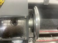
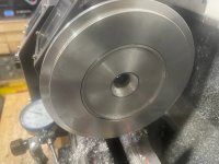
Last edited:
GTHound
Active member
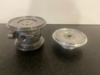
Glad you talked me out of TIG welding precision parts and challenging me to use a mechanical fastener. Oddly enough, I landed back at the fastening mechanism from the original design. In the picture below, on the left is the original bearing assembly. On the right is the new cast aluminum hub after some mashing with my bearing pressed in.
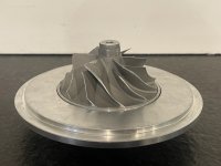
Below is the original hub, backplate and rotor.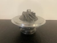
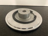
And here is the new cast aluminum bearing hub, backplate, and rotor.
I just copied the dimensions of the rim of the original bearing cartridge and will use the original O-ring and snap ring that it came with.

Below is the original hub, backplate and rotor.

And here is the new cast aluminum bearing hub, backplate, and rotor.

I just copied the dimensions of the rim of the original bearing cartridge and will use the original O-ring and snap ring that it came with.

GTHound
Active member
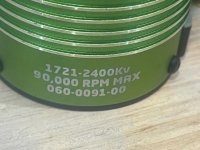 My new Castle motor came in, so I was able to prototype the stack with my upgraded metal parts (initial prototype was 3D printed ABS). Below is the hub that I cast in aluminum (after machining) mounted to the motor.
And here it is with the bearing and shaft in place.
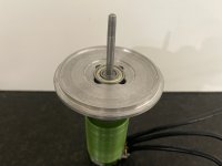
Below is the stack with the addition of the compressor wheel and factory o-ring.
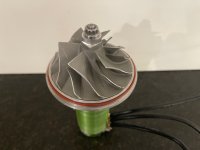
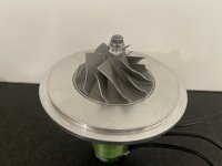
And here it is with the factory aluminum
Backplate dropped on the new hub.
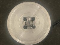
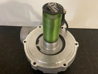
And the complete assembly viewed from the motor side.
Hopefully I can do some final measurement checks on clearances and run out and can spool it up later today and make some boost in the basement.
And we have boost once again!
Got up to about 2.5 PSI boost.
Then heard the dreaded metal on metal sound. I took it apart and am heading back to the lathe to drop the bearing about 20 thousandths of an inch for a bit more clearance.
Last edited:
GTHound
Active member
I have taken apart and reassembled the motor / compressor assembly more times than I can count. Each time, I have made a little adjustment / fixed a small problem. I am finally in a place where I am getting some data.
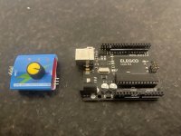
Also, I finally have switched from the servo tester (left) to the arduino type micro controller (right). At first I was using the arduino to read a PWM signal from a servo tested pot (this will eventually read the throttle position sensor PWM as input). Then, it took me a while to get the HobbyWing ESC to recognize the arduino (loaded servo library, sending right calibration signals). Next I tried ramping through several different throttle levels, a little as at a time as I break in the motor and get more confident as I work the kinks out of the system. Then I accidentally switched the arduino power and ground wires and smoked the voltage regulator. I used it for a little while longer, but it was getting hot, so i threw it in the trash.
I wish I had all the full data set in the data log, but alas I do not. I am missing pressure and motor temp.
That said, I have added the pressures the the data log below.
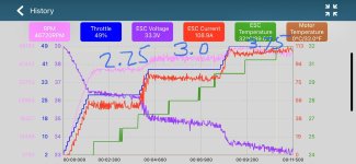
And below is a run that ramped to a little higher RPM. This one was at almost 60% throttle and delivered about 4.7 PSI ant 54K RPMs and about 4,200 watts, sound about like the realm of the torqamp.
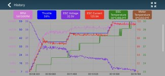
There is still a funny resonance lower in the RPM curve, but it seems to do alright if I just ramp through it. Seems to be smoother up at higher RPM. I’ll try 70% or maybe even 80% throttle tomorrow.
Also, I finally have switched from the servo tester (left) to the arduino type micro controller (right). At first I was using the arduino to read a PWM signal from a servo tested pot (this will eventually read the throttle position sensor PWM as input). Then, it took me a while to get the HobbyWing ESC to recognize the arduino (loaded servo library, sending right calibration signals). Next I tried ramping through several different throttle levels, a little as at a time as I break in the motor and get more confident as I work the kinks out of the system. Then I accidentally switched the arduino power and ground wires and smoked the voltage regulator. I used it for a little while longer, but it was getting hot, so i threw it in the trash.

I wish I had all the full data set in the data log, but alas I do not. I am missing pressure and motor temp.
That said, I have added the pressures the the data log below.

And below is a run that ramped to a little higher RPM. This one was at almost 60% throttle and delivered about 4.7 PSI ant 54K RPMs and about 4,200 watts, sound about like the realm of the torqamp.

There is still a funny resonance lower in the RPM curve, but it seems to do alright if I just ramp through it. Seems to be smoother up at higher RPM. I’ll try 70% or maybe even 80% throttle tomorrow.
Last edited:
GTHound
Active member
Well, I am back in town, so I finally had a chance do something this week on my project.
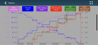
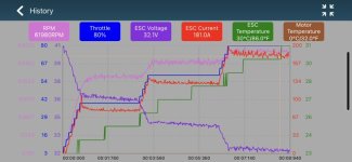
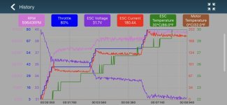
I charged my batteries last night. And my system has been running well with my 3 levels of boost 2 PSI, 4 PSI and 6 PSI. These boost levels correlate with the step levels on this data log. The boost is about 6 PSI at about 80% throttle, 180 AMPs and 60K RPMs.
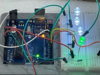
I now have a series of LEDs that indicate what is going on in the arduino micro controller:
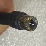
Additionally, I added my motor cooling system. Sadly, when I was installing my motor cooling system, I unplugged my motor power wires. And, when I plugged them back in, I must not have got one in all the way. When I ran it, it hit power level 1, power level 2, then on power level 3 the motor sort of stumbled (connnection melting). Then started again (molten metal forming connection). So I now have damage to both the ESC connection and the motor connection.
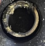
Additionally, the motor stopped quickly and the compressor nut came off and hit the housing. I cleaned it up and put it back together, but vibration is up and current draw increased by 10 Amps, so I will take it apart and hopefully adjust to get the shaft runout back under a couple thousandths.
I charged my batteries last night. And my system has been running well with my 3 levels of boost 2 PSI, 4 PSI and 6 PSI. These boost levels correlate with the step levels on this data log. The boost is about 6 PSI at about 80% throttle, 180 AMPs and 60K RPMs.

I now have a series of LEDs that indicate what is going on in the arduino micro controller:
- Power on LED
- Boost level 1 LED
- Boost level 2 LED
- Boost level 3 LED
- Charging LED (not shown to right)

Additionally, I added my motor cooling system. Sadly, when I was installing my motor cooling system, I unplugged my motor power wires. And, when I plugged them back in, I must not have got one in all the way. When I ran it, it hit power level 1, power level 2, then on power level 3 the motor sort of stumbled (connnection melting). Then started again (molten metal forming connection). So I now have damage to both the ESC connection and the motor connection.


Additionally, the motor stopped quickly and the compressor nut came off and hit the housing. I cleaned it up and put it back together, but vibration is up and current draw increased by 10 Amps, so I will take it apart and hopefully adjust to get the shaft runout back under a couple thousandths.
Last edited:
GTHound
Active member
Well, I cleaned up the motor contacts and it seems to work fine. It is probably for the better that I had the issue, as when I took the system apart, I was able to fix a few pesky problems.
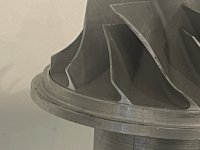
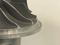
1) compressor wheel evenness from side to side. turns out my counter sinks were too close and it would drive the hub with the bearing slightly off center, which would slightly cant the compressor wheel. It now sits flush on both sides.
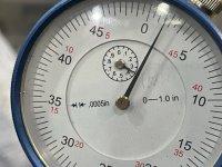
2) concentricity. I was able to get the shaft from 0.004” runout
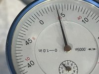 Back to to 0.002” runout.
3) I am replacing my slightly stripped socket head motor mount screws with new ones and will loctite on the compressor wheel nut.
I am back in business making about 1.4 bar (5.9 PSI boost) and vibration was significantly reduced.
Next steps are:
1) compressor wheel evenness from side to side. turns out my counter sinks were too close and it would drive the hub with the bearing slightly off center, which would slightly cant the compressor wheel. It now sits flush on both sides.


2) concentricity. I was able to get the shaft from 0.004” runout
 Back to to 0.002” runout.
3) I am replacing my slightly stripped socket head motor mount screws with new ones and will loctite on the compressor wheel nut.
I am back in business making about 1.4 bar (5.9 PSI boost) and vibration was significantly reduced.

Next steps are:
- Charging when not boosting (in between duty cycles). I have the step up transformer on order and the electronics already programmed
- Getting PWM signal from Holley Terminator X ECU into arduino.
- Upgrading hardware (MAP sensor) and A/F and timing tables in terminator software for boost.
- Tubing to connect compressor outlet to the inlet on my fuel injection system.
- Design and print housing for electronics
- Jumper or Replace ESC power switch with cockpit power switch
Last edited:
Jbrock
New member
I'm hoping to test that myself here soon. I'm using a P2 setup with a small 3.0L engine, so I'm gonna be testing if Braking current is enough to stop the motor before Surge or blowoff would need to happen. I think it depends on how much force you can apply to your setup without breaking anything from the sudden Jerk.Will I need a blow off valve? Or does the BLDC motor ramp down fast enough to negate the need?
GTHound
Active member
How are you going to evaluate the need for a blow off valve? Are you going to look in the data log at the manifold pressure when the Throttle position sensor goes below boost threshold? Or do you have other thoughts on how to assess?I'm hoping to test that myself here soon. I'm using a P2 setup with a small 3.0L engine, so I'm gonna be testing if Braking current is enough to stop the motor before Surge or blowoff would need to happen. I think it depends on how much force you can apply to your setup without breaking anything from the sudden Jerk.
GTHound
Active member
I am treading new territory here in electronics for me. I have been enjoying my new desk top power supply and just learning about constant current and constant voltage charging. But, I have only been charging half my battery at a time at 21.3 volts as my power supply is limited to 31 volts and can’t kick out the 12 x 3.55 volts = 42.6 volts required to charge my battery.
So, I ordered what is called a boost controller. It is essentially an electronically controlled step up transformer. It has potentiometers to adjust current and voltage output with a maximum of 30 amps.
I chose this one because:
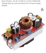
It just came in today and is bigger than I expected. I hooked my power supply up to the boost controller input and set it to 14.3 volts to match my alternator output. And sure enough, I was able to turn the CV screw and the output slowly decreased until it matched my target 42.6 battery charging voltage.
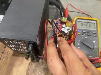
I will now wire up the boost controller, find a place to mount it and use it to charge my battery from my power supply in the basement and hopefully soon from my alternator in my car.
------update
I am using it now to charge my battery. It is interesting and different than charging directly with the power supply. Seems like the output voltage from the boost controller is just 0.06 volts higher than the battery voltage and it is slowly creeping up parallel to the battery voltage as it creeps up. I don’t see any changes from the other pots (UVP and CC). But, perhaps I don’t know what to look for.
So, I ordered what is called a boost controller. It is essentially an electronically controlled step up transformer. It has potentiometers to adjust current and voltage output with a maximum of 30 amps.
I chose this one because:
- Works with my input range of 14.3 volts from my alternator
- Adjustable to my target 42.6 volt battery charge voltage
- Current. My super charger will probably run a maximum of 6,000 watts / 746 watts per HP = 8 HP. I wanted to keep it charged even if it runs at 20% duty cycle, so wanted to get one of at least 6,000 x 20% = 1,200 watts. Hopefully I don’t have to run it that hard so I can keep it cooler.
- Price was right

It just came in today and is bigger than I expected. I hooked my power supply up to the boost controller input and set it to 14.3 volts to match my alternator output. And sure enough, I was able to turn the CV screw and the output slowly decreased until it matched my target 42.6 battery charging voltage.

I will now wire up the boost controller, find a place to mount it and use it to charge my battery from my power supply in the basement and hopefully soon from my alternator in my car.
------update
I am using it now to charge my battery. It is interesting and different than charging directly with the power supply. Seems like the output voltage from the boost controller is just 0.06 volts higher than the battery voltage and it is slowly creeping up parallel to the battery voltage as it creeps up. I don’t see any changes from the other pots (UVP and CC). But, perhaps I don’t know what to look for.
Last edited:
I think you may need one of these
Jbrock
New member
I was just going to have a controller "Map" the conditions of the Supercharger based on the RPM and Pressure data to determine if I'm in the Compressor Surge regionHow are you going to evaluate the need for a blow off valve? Are you going to look in the data log at the manifold pressure when the Throttle position sensor goes below boost threshold? Or do you have other thoughts on how to assess?
GTHound
Active member
I cranked up the cc knob on the boost controller and got it to feed 10 amps to charge my battery. But it quickly wattage dropped quickly because my battery was already charged. Seems to be working well.
I was just set up to do a healthy set of bench runs with temperature measurements to wear my battery out and test the charging system before installing into my car.
But….. on my first run, my pressure was looking great at first to motor levels but did not climb to 6 PSI as it should have and the amp draw was too high (200 vs expected 180 AMPS). And then the smell…. The smell of failure.
Another one (rotor) bites the dust!
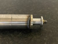
What causes this kind of mode of failure? It seems like it was arcing at the end of the rotor.
So, I see 3 possible paths forward.
1A) I just have bad parts, there was again a ton of balancing compound on the shaft end. Replace with like in kind but better balanced and perhaps fabricate a shrink to fit shaft.
1B) I have bad parts… move to TP motor? Or really step up to German motor? This could require refabrication of extension shaft, back panel. Or best case scenario just adjust spacer thickness.
2) I have a design issue. Honestly, it was running very smoothly, but maybe could move away from the set screw approach and go for the shrink on shaft extension like matnrach with a shorter extension shaft.
3) abandon direct drive? I know that WB has had similar issues to me with a similar approach but using the TP motor. I think he is still waiting on a new ESC
4) abandon project? This would be a shame, since the rest of the system seems so solid. So hoping to find a way forward.
I was just set up to do a healthy set of bench runs with temperature measurements to wear my battery out and test the charging system before installing into my car.
But….. on my first run, my pressure was looking great at first to motor levels but did not climb to 6 PSI as it should have and the amp draw was too high (200 vs expected 180 AMPS). And then the smell…. The smell of failure.
Another one (rotor) bites the dust!

What causes this kind of mode of failure? It seems like it was arcing at the end of the rotor.
So, I see 3 possible paths forward.
1A) I just have bad parts, there was again a ton of balancing compound on the shaft end. Replace with like in kind but better balanced and perhaps fabricate a shrink to fit shaft.
1B) I have bad parts… move to TP motor? Or really step up to German motor? This could require refabrication of extension shaft, back panel. Or best case scenario just adjust spacer thickness.
2) I have a design issue. Honestly, it was running very smoothly, but maybe could move away from the set screw approach and go for the shrink on shaft extension like matnrach with a shorter extension shaft.
3) abandon direct drive? I know that WB has had similar issues to me with a similar approach but using the TP motor. I think he is still waiting on a new ESC
4) abandon project? This would be a shame, since the rest of the system seems so solid. So hoping to find a way forward.
Last edited:
I thought you were using a shrink fit for the shaft. If not why not as it is the only sensible solution for an axial drive really. If you calculate the interference required it isn't much. It is easy to do if you are careful but you need the correct sized reamer if you don't bore it.
Also how concentric is your upper bearing? With your design it needs to be very good indeed, probably line bored.
Also how concentric is your upper bearing? With your design it needs to be very good indeed, probably line bored.
Last edited:
GTHound
Active member
Thank you for the thoughts. I did not have a lathe when I started the project, but now I do. I’ll have to go find the equations and figure out the required interference like you said. I could go either way with boring bar or reamer.I thought you were using a shrink fit for the shaft. If not why not as it is the only sensible solution for an axial drive really. If you calculate the interference required it isn't much. It is easy to do if you are careful but you need the correct sized reamer if you don't bore it.
Also how concentric is your upper bearing? With your design it needs to be very good indeed, probably line bored.
I am guessing that the shaft needs to be made with the hole for the motor shaft facing out towards the lathe tail stock and the shaft and threads towards the lathe chuck so that it can all be done in one go to maintain concentricity.
I finally got my head around the brass bushings and end play when taking my motor apart with the arced rotor.
Lastly, i am not sure how to measure the concentricity of the upper bearing. The hole that the bearing sat in was part of the back plate. The bearing itself, I did not modify. Or are you asking what grade the bearing is? It said it was high speed bearing. I was considering the end bearing to be more of an extra support and relying on the motor bearing.
I like your design and approach to shorten the shaft. Did you eliminate the motor end cap in your most recent design or just remove the bearing and bore it to a large diameter?
You must bore/ream the hole first with a steady and then turn the shaft with the hole acting as a support during turning.Thank you for the thoughts. I did not have a lathe when I started the project, but now I do. I’ll have to go find the equations and figure out the required interference like you said. I could go either way with boring bar or reamer.
I am guessing that the shaft needs to be made with the hole for the motor shaft facing out towards the lathe tail stock and the shaft and threads towards the lathe chuck so that it can all be done in one go to maintain concentricity.
I finally got my head around the brass bushings and end play when taking my motor apart with the arced rotor.
Lastly, i am not sure how to measure the concentricity of the upper bearing. The hole that the bearing sat in was part of the back plate. The bearing itself, I did not modify. Or are you asking what grade the bearing is? It said it was high speed bearing. I was considering the end bearing to be more of an extra support and relying on the motor bearing.
I like your design and approach to shorten the shaft. Did you eliminate the motor end cap in your most recent design or just remove the bearing and bore it to a large diameter?
The end cap of the motor is the same just a larger bore bearing and effectively nothing else. If the extra bearing in the backplate is not perfectly concentric then you are making a perfect rotating bend fatigue rig.
GTHound
Active member
Thank you for the blazing trails, the great insights and thinking, and sharing the fabrication techniques.You must bore/ream the hole first with a steady and then turn the shaft with the hole acting as a support during turning.
The end cap of the motor is the same just a larger bore bearing and effectively nothing else. If the extra bearing in the backplate is not perfectly concentric then you are making a perfect rotating bend fatigue rig.
I know it is obvious but when making the shaft, take your time. Take small cuts to avoid distortion even with a live centreThank you for the blazing trails, the great insights and thinking, and sharing the fabrication techniques.
GTHound
Active member
What are you using for a bearing? Are you still using the SPEC self lubricating plastic route or are you using a ball bearing now? When I searched for 100K precision bearing on McMaster, the only options that came up had a very small diameter (in the realm of 2 mm).
after sleeping on it, I am in the redesign mode with a goal to achieve run out under a thousandth of an inch.
after sleeping on it, I am in the redesign mode with a goal to achieve run out under a thousandth of an inch.
