2L Opel GT e-boost build

GTHound

Active member
I have found the forum to be quite helpful and inspirational. Thus, I am creating a thread for my build. It is sort of an R&D project, so will likely have quite a few iterations and twists and turns. That said, I hope to make some legitimate boost and serious gains in torque.
 
Last edited:
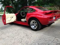
The car is a 1971 Opel GT. It comes with a 4 cylinder 1.9 liter Cam-In-Head engine that made somewhere around 89 HP, but the car is quite light at around 2,000 pounds.

The car was my uncles who died a weak decades ago. The car was quite rusted out (you could see the road if you pulled up the floor mats). My dad and I highly customized it when restoring it. The car is now 8 inches wider than it used to be to accommodate the wheels, shaved door handles, tunnels tail lights and license plate, custom aluminum grill, a narrowed Fiero back wing, custom leather interior, etc. Below is a quick pic from my profile.
IMG_2254.jpeg
My goal is to make it drive like it looks
(at least in my minds eye). This means we should be in the realm of 180-200 HP and 200 foot pounds of torque. The engine is currently a 2.0 liter, with a little higher compression and a big valve head (think Chevy 350 valves). I wanted to get rid of the breathing problems / limitations of the down draft intake manifold and spent the last year building a custom fuel injection system that flows well with modern Bosch fuel injectors, and a modern Holley Terminator X engine management system. I am quite pleased with the result and think I am in the 130-140 HP realm now based on the data logs. This intake and engine management system not only working great, but is quite well suited for receiving and controlling the electronic boost. Though I might need to switch from the 1 bar to the 3 bar manifold pressure sensor.

I am in the process of planning a 2.4 liter engine build with a stroker crank (welded and offset ground 0.250” with 10:1 compression, forged pistons, high flow racing head etc). Looking for more torque, and this should deliver. But it is taking a long time (several year project) to procure / fabricate custom parts.

In the meantime, here we are chasing more torque with E-super charger build for this car.
 
Last edited:
I started the project by making an Excel spreadsheet with volumetric air flow as a function of RPMs and boost pressure for my engine as well as compression ratio and horsepower estimates. Then, studied the torqamp, which although a bit pricey is quite similar to what I am looking to build.

Next I got inspired by this forum. Then of course there was the spreadsheet of the list of components, options, and prices.

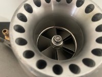
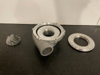
Then, I got hungry for some hands on learning and wanted to get a compressor and volute housing to play with. I could not find a reasonably-priced, viable super charger for my application. So, I started looking at turbo chargers. I spent a lot of time staring at compressor maps and learning how to read them.

However, the rules of what we are trying to do here are different, so the selection process was less than clear. The turbo (exhaust side) will not be used. The surge line is sort of irrelevant, because you can program the motor to start spinning when you want. What I used as my primary guide was to find a compressor that delivers target boost pressure at relatively low RPMs on a decent efficiency island. That guided me to a relatively large compressor wheel (82 mm diameter) with high edge velocity at only 50K RPMs. Which is quite different than a typical turbo I would look for on a car like this, such as a K04, which would be small in diameter, spool up fast, and crank over 150K RPMs and deliver about a bar of boost at redline.

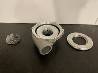
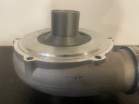
I ended up with a GT3582 Turbo Charger with an AR.70 volute housing for $110 off of eBay with free shipping.
IMG_9733.jpeg
 
Last edited:
Thanks for posting this - I wrote a long reply asking for this stuff in the battery thread, then I saw you were already doing it here. Can you post pics of the the car's engine and your surrent e-boost setup and your datalogs and stuff here? I feel they're getting lost in the battery thread, and it's easier to keep one project straight in it's own thread.

I'm eager to see how this one goes.
 
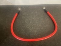
Today, I completed the much needed battery lead upgrade. I had performed an initial test with some super short super undersized 18 ga wires when I was anxious to see if the battery worked and could get the ESC powered and motor to spin. Those were way undersized but already had jumper cable ends on them. And now, I probable went too far. Here is a pic of the extreme wire gauge make over.
IMG_0476.jpeg
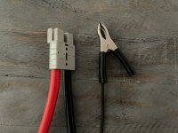
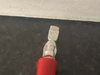
I ordered some 4 gauge copper battery wires that were pre-terminated on each end and an Anderson type connector for each of getting my battery in and out of my car.IMG_0455.jpeg
I cut and removed one of the ends from each wire.
IMG_0457.jpeg
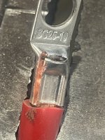
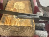
Then, I needed to figure out how to crimp the Anderson connectors onto both the new battery cables and the ESC power wires. Buying a dedicated tool for this job was too expensive for me, so, I figured that I would make a crimping tool. First, I took a piece of 1/2” x 3/4” steel and drilled a ~ 5 mm hole all of the way through it. Then I drilled a 7 mm hole maybe a third of the way the way through from each side and cut it in half with a band saw.
IMG_0468.jpeg
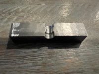
The result was two halves that looked like this. The raised area in the middle is what I planned to use to crush the connector onto the wire. IMG_0478.jpeg
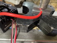
So I placed it on a 20 ton shop press and gave it a try.IMG_0473.jpeg
The result looked like this. I was quite pleased. IMG_0471.jpeg
So, now I have a high quality connector which provides ease of use and huge wires that should be the last thing to get hot in my power chain.

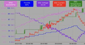
Of course, I was anxious to spool it up. I now can reliably ramp up to over 3 PSI at about 50% throttle, 50K RPMs and about 100 amps at 33 volts. IMG_0477.jpeg
So, I eliminated 2 problems / chinks in the armor this weekend.
  1. I upgraded my power wires to prevent potential touching, ease of connection, and suitable heavy duty amperage.
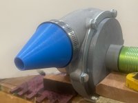
  2. I kept my 3D printed Snorkus form blowing off at about 3 PSI with a heavy duty clamp.
    IMG_0480.jpeg
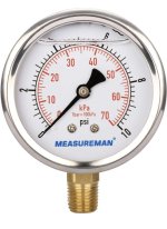
However, i was getting an error message on the digital manometer above 3 PSI. I thought it may have been a weird instability, but turns out that the spec on my digital manometer is limited to +/- 3 psi. I don’t want to fly blind, so I need a way to measure pressure. But, I don’t want to spend a lot of money on it, as I will have a built in digital boost gauge in my EFI system. Thus, I ordered this 10 PSI analog pressure gauge to get some data / learning at higher boost this week.
IMG_0481.jpeg
 
Last edited:
I really like your crimp solution. I have a hydraulic crimper, but it's designed for metric wiring - so not all awg cables fit the dies well. You've given me a great idea on how to make the correct dies fairly easily. Thanks! Though the more I crimp heavy cables the more I like this solution:


So it looks like (based on the data in the battery thread) that you're pulling 30 amps more (10% more throttle) and seeing 1 volt less drop, correct? That's an imrovement, but still a little more voltage drop than I'd like to see - 5 volts at 100 amps isn't terrible, but it could be better. Have you tried measuring voltage at the battery during one of these pulls? When I build a pack, I'm pretty fastidious about cleaning the busbars abrasively right before I install them, and I now pretty much always use noalox or something similar. I'd go through several pulls checking voltages at various cells to see if there's one connection that's hotter than another. An IR camera would find that fast, but a good IR camera isn't cheap, unfortunately (I've bought 1, but returned it when I wasn't satisfied with its performance - I'm looking for one that can handle over 1,000* F so I can cheak header tubes and exhaust components as well).

None of this if a huge deal - the huge deal is that you're making great progress! Looking forward to your next update.
 
Thanks for the kudos on the homemade DIY heavy duty wire crimper. It worked great, and the cables are the least of my worries now. That said, I do like the looks and flexibility of the Amazon crimper. Thanks for the link. I need to ponder how to assess my battery build. It came with solid copper bus bars and screw in terminals, which is one reason I chose those batteries.

On to the really exciting progress! The 10 PSI gauge showed up. So, I hooked up the new analog boost gauge, put on my safety gear, and spooled up the e-turbo way beyond anything I had tried before…

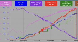
On the first pull, I hit 4 PSI (woohooo), then 4.5 psi, then 5 psi, then 6 psi, then 7 psi. So I have achieved my design goal for pressure. But each run was ended prematurely by the ESC when the voltage dipped to 30. This is what Alex and other brilliant folks on this forum foresaw. Below is a snippet of one of the runs all which look almost exactly the same.
IMG_0487.jpeg
So for each run, I max out between 58-59K RPM and 6-7 PSI at almost 167 amps when the battery gets down to 30 volts.

My next challenge is how to maintain boost at a steady state for ~5-10 seconds. Although much of my boost will be shorter spurts than that.

So the limiter of my set up and is now my sub $200 budget battery (although, it did get me up and running and was fun to build.) My next step is to charge my battery fully, as I have not charged it since I built it and have had 51 pulls in the data log on it.

I have not invested in a battery charger that can deliver the 3.65 x 12 cells = 43.8 volts. So, right now half of my battery is charging at 3.65 x 6 = 21.9 volts. I’ll get both sides charged up and get some data with a full battery charge and see if that makes a difference.

Else I figure will explore one of the following paths:
  1. See what boost level I can maintain without going under 30 volts
  2. Add a couple of cells? Perhaps that could offset the precipitous decline. Or maybe it is about percent voltage drop.
  3. Explore other battery options (in which case my current battery becomes my car battery, but requires different set of bus bars).
————— UPDATE —————

I was grateful that the ESC auto protect feature worked and kept my batteries from over discharging and frying my cells.. But, I wanted to verify the 30V lower limit from todays trials. I thought it kinda made sense 30V / 12 cells = 2.5 volts per cell.

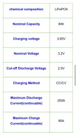
But,I have good news and more paths to explore with this budget battery set up. Here are the stats on these Headway cells form the battery hookup website. So the cutoff discharge voltage is 2 volts, not 2.5 volts.
IMG_0488.jpeg

If I understand this correctly, my lower limit is not 30 volts, but rather 12 cells x 2.0 volts = 24 volts! So I have a lot more voltage sag available before frying my batteries. Don’t get me wrong, I don’t want voltage sag, but I will take some extra amps if I can find them to increase the operating range of my system.

If I am getting 167 amps / 9 volt drop = 18.5 amps per volt drop. If I allow 5 more volts drop, I should be able to get theoretically another ~ 90 amps or so. Currently 167 amps x 30 volts = 5,010 watts / 746 watts per hp = 6.7 HP. Another 90 amps would theoretically get me to 250 Amps x 25 volts = 6,250 watts / 746 Watts per HP = 8.4 HP. That might give me just enough breathing room (pun intended) with my current set up.

Next step is to reprogram ESC for 27 volt cut off and see how things behave then try a 25 volt cut off. I will post the data for these runs. Then after that, I will get a micro- controller involved in sending the PWM signal and target 3 seconds, then 5, then 7, then 10 seconds continuous.
 
Last edited:
It totally worked! I did 3 things 1) I charged my battery, 2) reprogrammed my ESC to a lower cut off voltage, and 3) I labeled my battery so I remember how to charge it without doing calculations.

1) Charging the battery was easy thanks to the easy disconnect with the Anderson connector.

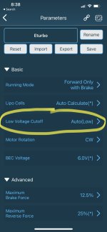
2) Reprogramming the ESC was easy using the blu tooth module and the HobbyWing iPhone app. I left the auto configuration on the number of battery cells, but changed the cut off voltage from intermediate to low.
IMG_0491.jpeg

That did the trick. I connected the battery to the e-super charger with the Anderson connector and did a quick test run.

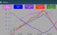
It ramped up smoothly to 6 PSi and then back down without the ESC bailing due to low battery voltage. Here is a picture of the data log from the run.
IMG_0493.jpeg
Looks like a record of 61,220 RPM at 182 amps. higher voltage (due to the freshly charged battery). So the result is more power 182 amps x 32.4 volts = 5,897 watts. It did seem like the current, voltage, and pressure held steady when I flattened out the throttle for a few seconds.

This is starting to look like a potentially viable system for my application. The next goal is to reach 200 Amps or 6,000 watts. Then I will see if I can achieve a longer boost time at high output pressure.

I am quite pleased that the current set up has promise of being viable, rather than trying to research, source, and fund a new battery option.
 
Last edited:
Awesome! I'm really impressed with the rpm you're able to hit. As for the battery, when you're internal resistance limited, it's better to have fewer cells in series. Do you have enough cells to do a 2p setup? That would in theory cut your voltage drop under load. LiFePo4 cells are a good choice because they're safer and they're actually harder to damage than more conventional lipos. I'm also wondering if you have one or more weak cells. While not super likely, it's definitely possible.

I do have a question - did your boost gauge flutter under load? It looks to be liquid filled. Can you post a link?

Congrats again!
 
Awesome! I'm really impressed with the rpm you're able to hit.
I was excited to break the 60K RPM barrier. That said, I hope that there is more potential beyond the 61,200 RPM limit. Although a best for my system, perhaps it was just the limit of the day (I still had more room on the potentiometer). I will make a few more runs today and see if we can do better for RPMs and achieve longer sustained runs that mimic my driving habits.
As for the battery, when your internal resistance limited, it's better to have fewer cells in series. Do you have enough cells to do a 2p setup? That would in theory cut your voltage drop under load. LiFePo4 cells are a good choice because they're safer and they're actually harder to damage than more conventional lipos. I'm also wondering if you have one or more weak cells. While not super likely, it's definitely possible.
Yes, I am running a 12S2P set up. So there are 24 cells total. I am running side by side chains of 12 cells in parallel. 12 cells x 3.3 nominal voltage is the ~ 39.6 starting voltage.
IMG_0494.jpeg
Since they are 8Ah batteries, I should have a 16 Ah battery. Latest thinking is that I have 16 Ah x 30 volts x 60 min per hr = 28,800 watt mins /6,000 watts = 4.8 minutes of boost without charging or safety factors incorporated.
That's an improvement, but still a little more voltage drop than I'd like to see - 5 volts at 100 amps isn't terrible, but it could be better. Have you tried measuring voltage at the battery during one of these pulls? When I build a pack, I'm pretty fastidious about cleaning the busbars abrasively right before I install them, and I now pretty much always use noalox or something similar. I'd go through several pulls checking voltages at various cells to see if there's one connection that's hotter than another.

None of this if a huge deal - the huge deal is that you're making great progress! Looking forward to your next update.
As a quiet activity this morning, I went and check all of the battery terminal screws and found one loose one, another questionable one, and the rest seemed ok. I am not familiar with Noalox, but just did some quick research and looks like it is available at Home Depot. I think I’ll pick some up today. Then I will clean up terminals a bit and apply. Maybe it helps voltage drop, it worst case should help maintain battery performance over time. Seems like a no brainer. I am just new to all of this, so thanks for the tips!
I do have a question - did your boost gauge flutter under load? It looks to be liquid filled. Can you post a link?
I have not seen my digital manometer or the analog pressure gauge flutter. Seems to be very smooth. I know that they claim this is an “anti surge compressor design”. I believe that is why they have all of the holes at the volute housing inlet. I wonder if that could have anything to do with it?
IMG_0423.jpeg
thanks for all the help and encouragement.
 
Last edited:
I use fine sandpaper to clean the contacts before I bolt them on with noalox - something in the realm of 240-600 grit (usually whatever I can find first). There's about a half a volt difference between copper and aluminum on the galvanic scale, with copper being more noble than aluminum (meaning the aluminum will corrode when the two are in contact).

Looking at the compressor map, it looks like you're already in the ballpark of 210-230 hp with your engine, fwiw. I'd say for first tests, once you go through the connections, let it eat (on the car). Not sure if you'd want to replace that 3d printed back plate with an aluminum one first... I probably would.
 
Good news and bad news. The good news is record runs today and my battery looks viable for my system. The bad news is that my motor rotor flew apart.

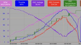
The first pull of the day was a record in many ways. It was so good. It ramped right up, did a hold, and ramped right down. It spooled smoothly to 66K RPMs at 95% throttle, blew past my 200 amp target at 234 amps and 30.4 volts for 7,100 watts. I wish I could have locked it in at that setting, which was so good.

IMG_0510.jpeg
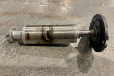
Then, for the next run, instead of running like I usually do, I moved away from the live data log and instead took a video with my left hand of the pressure gauge and volt meter and controlled the potentiometer with my right hand. I was not trying to, but accidentally dialed in 100% throttle and saw “a little puff of smoke”. It turns out that smoke was actually magnet dust from the rotor. The castle creations 1721 2400 kV motor was said to have an upper limit of 80K and I got close to 70K, but it should not have flown apart. Here is a quick pic of the damage. IMG_0505.jpeg
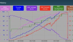
And here is the data log of the run of infamy. It pulled over 300 amps, but did not really spool much higher (it stayed under 70K RPMs). In fact when it went to 100% throttle, the RPMs actually decreased. Although that may have been after the rotor self destructed. The pressure gauge peaked at about 7 PSI of boost and the voltage on the battery was almost exactly the same as the voltage on the ESC data log as far as I can tell.IMG_0511.jpeg
The battery was cool. My big power wires were cool. The ESC was even cool. Even with the big amp pull. I checked the continuity of the motor windings and they were good. So I did not melt the motor windings down with too much power. I guess this was a fair load test for the Hobbywing Max 4. It is supposed to handle 300 amps continuous and something crazy like a peak of 2000 Amps, so no surprise it faired well.

I sent the motor in to castle for “repair” but the email they sent back said they might not get back to me for 8 weeks. Arghh! What a bummer and way to ruin a summer!

So, I am out of business for a while. In the meantime, I will be working on fabricating aluminum parts (spacer and back plate) as well as working on the electronic control system, and step up transformer charging system that I will need to run the system in my car.
 
Last edited:
Uh oh. The weekend is upon us and I have nothing to build. But wait, maybe I can make constrained progress. While I am waiting on a new motor rotor, I decided to design and 3D print some trays to hold my various electronic components.

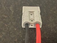
I like the way my big 4 gauge battery wires fit the Anderson connector. But I was concerned about the 8 gauge wires heading to the ESC. So I designed and printed some plastic shrouds to make sure the ESC power wires stay snugly in the Anderson connector.
IMG_0539.jpeg

And here they are installed in between the Anderson connector and the power wires.
IMG_0515.jpeg
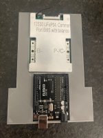
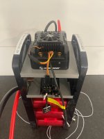
Next I fabricated a tray to hold the battery management system and arduino microcontroller.
IMG_0533.jpeg
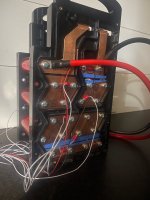
I designed it to slide into a slot in my 24 cell LiFePO4 battery pack.

IMG_0534.jpeg
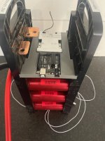
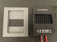
I will likely design and 3D print a middle shelf for my step up transformer to charge the battery off of the cars 14.3 volt alternator. Then, I designed an upper shelf to hold the ESC securely in place.IMG_0541.jpeg
It is designed to sit perched atop the battery stack to give it breathing room and elevation to attach the short wires to the electric super charger motor.
IMG_0537.jpeg
In my opinion, This is a pretty cool tech stack, but alas, beauty is in the eye of the beholder. I plan to secure the whole assembly to my cars belly pan in front of the radiator. And it can all be removed easily with the handles built into the battery holder.
 
Last edited:
Oh no I understand your feelings! My ESC is out for repair for about 9months now 🥲 hope I will get it back this summer to try my 2.0 set up. I am impressed too qith your data! Don’t remember how high my rpm was but I think yours a little faster! Can’t wait to try my castle motor
 
Oh no I understand your feelings! My ESC is out for repair for about 9months now 🥲 hope I will get it back this summer to try my 2.0 set up. I am impressed too qith your data! Don’t remember how high my rpm was but I think yours a little faster! Can’t wait to try my castle motor
Thanks WB, I heave really enjoyed your journey and am excited for you to get back in the game. If I were wealthier, I would just send a new ESC to you. I too excited both about the castle motor and the cooling that you have for it!

Out of curiosity, 1) how much boost were you able to run and 2) how many amps did it pull? 3) how long did you have your boost up and running before the motor issue?

Also, I hope that we can make our direct drive option work. We have both had a rotor fly apart on us. I hope those are outliers and we can get some good life out of our systems and make direct drive work. If we can’t make the made in China motors work, we may need to look at the European Option LMT made in Germany motors.
 
Well, still no word on my electric motor. But I did get a call from my crank shaft company, and the offset stroker crank to make my 2.0 liter into a 2.4 liter is complete.

In the meantime, I decided to follow WBs lead on aluminum adaptor plate between the motor and housing. But, I do not have a big aluminum plate or CNC or any thing like that. But, I have cobbled together some capability that I will try to leverage in this build.

My turbo charger came with an aluminum back plate with a big hole in the middle to mount the compressor assembly in with a big snap ring.
IMG_9733.jpeg
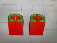
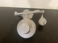
I am thinking about using that aluminum back plate and then casting and machining and adaptor and TIG welding it to the factory backplate. In the picture below, I am going to try to make the dark gray plastic pieces out of aluminum.

IMG_0608.jpeg
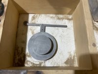
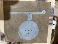
First step was to design and print a mold.
IMG_0561.jpeg
Then ram up the mold in green sand (homemade mixture or sand and bentonite clay from cat litter) along with the gating system.
IMG_0562.jpeg
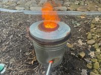
Melt down some high silica aluminum from a cast alloy wheel in a home made garbage can foundry. IMG_0601.jpeg
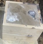
and pour the molten aluminum into the mold. I was able to keep the sprue full.
IMG_0602.jpeg
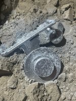
So, I was pretty pleased with the surface quality.
IMG_0603.jpeg
Tomorrow I will cut off the gating system and try to machine it down to proper dimensions.
IMG_0604.jpeg

And hope that there isn’t too much of an issue with porosity.
 
Last edited:
I received the email from Castle today that I needed to pay the replacement price for the motor and shipping. But I called and talked to them and the repair department lady literally had my motor in her hand and said it was probably a bad motor (could tell by the amount of balancing compound on the rotor). So they are sending out the new one tomorrow. I hope to have it by the weekend. But if not, it should arrive on Monday.

Woohoo! Looking forward to making some more boost in the basement and getting it to run on arduino in preparation for installation on my car!
 
Thanks WB, I heave really enjoyed your journey and am excited for you to get back in the game. If I were wealthier, I would just send a new ESC to you. I too excited both about the castle motor and the cooling that you have for it!

Out of curiosity, 1) how much boost were you able to run and 2) how many amps did it pull? 3) how long did you have your boost up and running before the motor issue?

Also, I hope that we can make our direct drive option work. We have both had a rotor fly apart on us. I hope those are outliers and we can get some good life out of our systems and make direct drive work. If we can’t make the made in China motors work, we may need to look at the European Option LMT made in Germany motors.
About 7psi with my tp motor with 55k rpm if I remember correctly! Maybe little more rpm. It’s been too long so I really don’t remember the amps I was pulling. There’s some pictures here and there on the forum! Finally it was not a motor issue but a ESC issue. I first think it was the motor so I bought the castle motor but still had the same issue.
 
Top