2L Opel GT e-boost build

What are you using for a bearing? Are you still using the SPEC self lubricating plastic route or are you using a ball bearing now? When I searched for 100K precision bearing on McMaster, the only options that came up had a very small diameter (in the realm of 2 mm).

after sleeping on it, I am in the redesign mode with a goal to achieve run out under a thousandth of an inch.
I am using rc bearings although they are not rated for 100k as my duty cycle is low. The top bearing is Peek but is not a true bearing just a deflection limiter and most likely does very little. The OE spec of the motor bearings don't appear to be rated to 100k either
 
Last edited:
I think I calculated the interference at about 0.0008" with a tolerance of +/- 0.0005" for an 8 mm shaft. I would set the compound at a very shallow angle to the shaft and use it advance the bit. Making cuts of a few ten thousandths with the micrometer dial on the cross slide is will be tough.
 
I think I calculated the interference at about 0.0008" with a tolerance of +/- 0.0005" for an 8 mm shaft. I would set the compound at a very shallow angle to the shaft and use it advance the bit. Making cuts of a few ten thousandths with the micrometer dial on the cross slide is will be tough.
 
That sounds about right. I ended up drilling to 7.90mm and reaming 7.980mm. This gave me near as damit 10mics interference. Also ensure that there is a slight flat on the shaft so that the air can escape when shrinking it on.
 
I cranked up the cc knob on the boost controller and got it to feed 10 amps to charge my battery. But it quickly wattage dropped quickly because my battery was already charged. Seems to be working well.

I was just set up to do a healthy set of bench runs with temperature measurements to wear my battery out and test the charging system before installing into my car.

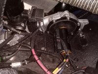
But….. on my first run, my pressure was looking great at first to motor levels but did not climb to 6 PSI as it should have and the amp draw was too high (200 vs expected 180 AMPS). And then the smell…. The smell of failure.

Another one (rotor) bites the dust!
View attachment 710

What causes this kind of mode of failure? It seems like it was arcing at the end of the rotor.

So, I see 3 possible paths forward.

1A) I just have bad parts, there was again a ton of balancing compound on the shaft end. Replace with like in kind but better balanced and perhaps fabricate a shrink to fit shaft.

1B) I have bad parts… move to TP motor? Or really step up to German motor? This could require refabrication of extension shaft, back panel. Or best case scenario just adjust spacer thickness.

2) I have a design issue. Honestly, it was running very smoothly, but maybe could move away from the set screw approach and go for the shrink on shaft extension like matnrach with a shorter extension shaft.

3) abandon direct drive? I know that WB has had similar issues to me with a similar approach but using the TP motor. I think he is still waiting on a new ESC

4) abandon project? This would be a shame, since the rest of the system seems so solid. So hoping to find a way forward.
My first suspicion would be imbalance or an alignment problem causing the rotor to flex a bit. If you want to stick with direct drive, I'd follow matnrach's guidance.
 
That sounds about right. I ended up drilling to 7.90mm and reaming 7.980mm. This gave me near as damit 10mics interference. Also ensure that there is a slight flat on the shaft so that the air can escape when shrinking it on.
were you using an adjustable reamer?
 
At first I was looking for metric 7.98 mm reamer and it was hard to find. Instead I tried searching for 0.3140” reamer, for which I found a Drill America version for $22 on Amazon.

Check my math.

8 mm / 25.4 mm per in = 0.31496”
~ 0.3150” - 0.3140” = 0.001” Interference equals roughly 25 microns

Or

0.3140” * 25.4 mm per in = 7.976 mm
Which rounds up to the 7.98 mm reamer
0.024 mm interference is 24 microns

My hunch is that i will have a bit of wobble and end up with less interference than that.
 
Last edited:
Your shaft will not be 8.000mm. You must measure it with enough accuracy. 0.01mm resolution is not good enough
I think 24 mics is too much as you would have to heat it up to a really high temp and it would most likely cool down as you try and fit it on and stick (also probably overstress the material with that much interference)
Unfortunately you are entering a world of high precision engineering where you need to measure parts to a high degree of accuracy.
Also you dont really know what size hole your reamer will produce in your environment so you need to do a test hole and measure that accurately as well. A few microns out on the shaft and bore and you will either loose all your interference of have too much and possibly yield the material (although that is a bit more unlikely)
That is why I was a bit reluctant initially to make the shaft myself, not even including the difficulty of keeping it all concentric and a small home lathe!
That is just my thoughts and of course I could have overthought it all and you you may get away with less precision.
 
Last edited:
Thank you for all of the thoughtful comments. Quite helpful in guiding thinking and technique around fabrication.
Your shaft will not be 8.000mm. You must measure it with enough accuracy. 0.01mm resolution is not good enough
Yep, I plan to measure the shaft of my new motor once it is in hand with 0.0001” caliper.
Also you dont really know what size hole your reamer will produce in your environment so you need to do a test hole and measure that accurately as well
Agree. I added some precision shims last night to my lathe tailstock to get height match less than 0.001” with the headstock. And I ordered the 0.3140” reamer so I can start the learning process.

I plan to do some test shrinking on some test material that matches the diameter of the motor shaft.

I have a tenths caliper, so I can measure shaft OD with reasonable precision. But, how did you come up with a technique to measure the ID of the extension shaft hole?

Here’s to learning our way to high precision with hobby grade equipment!
 
Last edited:
Thank you for all of the thoughtful comments. Quite helpful in guiding thinking and technique around fabrication.

Yep, I plan to measure the shaft of my new motor once it is in hand with 0.0001” caliper.

Agree. I added some precision shims last night to my lathe tailstock to get height match less than 0.001” with the headstock. And I ordered the 0.3140” reamer so I can start the learning process.

I plan to do some test shrinking on some test material that matches the diameter of the motor shaft.

I have a tenths caliper, so I can measure shaft OD with reasonable precision. But, how did you come up with a technique to measure the ID of the extension shaft hole?

Here’s to learning our way to high precision with hobby grade equipment!
I cheated and borrowed a Mittotoyo digital bore mic for this sized hole
 
Regarding my burned motor rotor.
IMG_0858.jpegI talked to my motor consultant today, and he provided some great thinking.

Here are some key insights:
  1. Windings get hot rapidly under high load (I am running in the 6,000 watt realm) and transfer heat inward to the rotor and outward to the casing. The rotor gets hot and increases in size due to thermal expansion and may even contact the windings.
  2. Bigger motor windings have more copper mass and thus higher heat capacity, and thus heat up more slowly.
  3. But bigger motor diameters are limited in RPM due to centrifugal force
  4. Balance out points 2 and 3 above by getting long motor with more copper mass and thus better heat handling, but with smaller diameter to enable high RPM.
  5. Add cooling system to draw heat out.
  6. My castle motor has ABEC 5 bearings
And here is my plan:
  1. Get replacement Castle 1721 2400KV (on the way)
  2. Fabricate interference fit 8 mm shaft to improve concentricity, reduce runout, and maintain balance.
  3. Get higher quality support bearing.
  4. Add cooling jacket by adding 0-ring sealed sleeve on the outside of casing and run liquid coolant.
  5. Consider programming an algorithm to limit run time (and thus limit heat input into the system)
  6. If this doesn’t work… abandon the castle 1721 2400kv and narrow down options on alternate motor
  7. Or consider non direct drive options (but I am hoping that if torqamp and members of this forum can get a viable direct drive that I have hope).
 
Last edited:
I talked to my motor consultant today, and he provided some great thinking.

Here are some key insights:
  1. Windings get hot rapidly under high load (I am running in the 6,000 watt realm) and transfer heat inward to the rotor and outward to the casing.
  2. Bigger motor windings have higher heat capacity (more copper mass).
  3. But bigger motor diameters are limited in RPM due to centrifugal force
  4. Balance out points 2 and 3 above by getting long motor with more copper mass and thus better heat handling, but with smaller diameter to enable high RPM.
  5. Add cooling system to draw heat out.
  6. My castle motor has ABEC 5 bearings
And here is my plan:
  1. Get replacement Castle 1721 2400KV (on the way)
  2. Fabricate interference fit 8 mm shaft to improve concentricity, reduce runout, and maintain balance.
  3. Get higher quality support bearing.
  4. Add cooling jacket by adding 0-ring sealed sleeve on the outside of casing and run liquid coolant.
  5. Consider programming an algorithm to limit run time (and thus limit heat input into the system)
  6. If this doesn’t work… abandon the castle 1721 2400kv and narrow down options on alternate motor
  7. Or consider non direct drive options (but I am hoping that if torqamp and members of this forum can get a viable direct drive that I have hope).
 
All sounds sensible. I have fitted two of the fan assisted heat sinks with thermal paste and although my duty on the motor is low it maintains virtually ambient body temperature. The fans run all the time but I may mod the code with a timer post motor activation.
 

Attachments

  • 1691136047147_IMG_20230804_065248.jpg
    1691136047147_IMG_20230804_065248.jpg
    426.2 KB · Views: 12
All sounds sensible. I have fitted two of the fan assisted heat sinks with thermal paste and although my duty on the motor is low it maintains virtually ambient body temperature. The fans run all the time but I may mod the code with a timer post motor activation.
I look forward to the day I have a reliable system on my car like you!

Do you know how many amps you pull and for how many seconds on typical spool up? I am just trying to get a sense of the area under the curve in terms of heat input.

The motor consultant based on boat racing experience seemed to think that getting the heat out fast was important. So, I mentioned aluminum heat sink and he did not think that was fast enough for high powered (200-600amp realm) pulls. Thus the suggestion of water cooling and even cooling the water below room temp for the higher current loads.
 
Last edited:
I look forward to the day I have a reliable system on my car like you!

Do you know how many amps you pull and for how many seconds on typical spool up? I am just trying to get a sense of the area under the curve in terms of heat input.
I have not accurately measured the current, only on a bench test for single phase comparison purposes but the spec of the motor is 300A and that agrees reasonably with the single phase crude measurement. The average duration of the spool is only around 3s although this could repeat maybe 3 times in 15s (worse case)
 
I am trying to get my head around how much cooling I need. Check to see if I am thinking about this correctly. If I pull ~ 190 amps @ 32Volts that is about 6,000 watts. 6,000 watts x 5 seconds = 30,000 joules. And the thermal capacity of water is about 4.2 J/g degrees C which has 4.7 times more heat capacity per gram degree C than aluminum (0.89). So, if I have a half liter of water as coolant 500g x 4 J/g degrees C= 2,000 joules per degree C thermal capacity. So, if I could get 70% of the heat to go into the water, the water would increase 70% * 30,000 joules / 2,000 joules per degrees C = 10 degrees C. So, I believe that puts me in the realm of reasonableness. What I am trying to do is make a large thermal capacitor to prevent the motor from getting damaged from short term heat spikes and cool it down between use cycles.

I just printed a 3D sleeve that will fit over the motor that will seal at the ends with o-rings. I may make an aluminum one eventually, but will go with rapid prototyping for now.
IMG_1045.jpeg
Then, I am thinking about adding a cooling system for a computer CPU that has a radiator, electric fans, and circulation pump. Maybe something like the item below. The radiator and cooling fans will accelerate the rate of heat dissipation. And if I need more impulse cooling, I could just add a reservoir with more water.

61C3xuyoyQL._AC_SL1200_.jpg
 

Attachments

  • 1691184726721.png
    1691184726721.png
    122.3 KB · Views: 2
Last edited:
Top