You are using an out of date browser. It may not display this or other websites correctly.
You should upgrade or use an alternative browser.
You should upgrade or use an alternative browser.
2L Opel GT e-boost build
- Thread starter GTHound
- Start date
GTHound
Active member
I was excited to make another iteration of the extension shaft today with my newly set-up lathe. Every-time I seem to think this could be the one. All was looking better than ever…
UNTIL I took out the live center.
I could not believe it as the near-zero-run-out shaft that was spinning so true bent in the 1/4” shaft area right before my very eyes!
After researching this a bit, I have learned that there are stresses in the metal that get “released” when it gets hot / machined etc. I get a sense that in my setup there was nowhere for those stresses to go.
Here is a list of some of my my potential causes and plan for the next iteration. I think that the last one may be most important.
This shaft | Next Shaft | |
| Chucked up deep / full length of jaws | Chuck up shallow.. maybe 1/2” max | |
| Longer piece than needed | Go back to minimum length | |
| Cranked down hard on chuck key | Reasonable force. Perhaps using copper foil at jaws | |
| Low grade hot rolled steel (for practice until new stock arrives) | 1018 steel | |
| Wonky wobbly piece of stock difficult to chuck properly | Start with round stock or skim coat it before chucking | |
| 5/8” stock | 1/2” stock to minimize material removed / heat | |
| Tight live center (that got tighter with heat) | just enough tension for live center to spin | |
| Deep, heavy cuts | Shallower cuts to minimize heat | |
| Rough in to 0.020” over then let cool before finish passes |
Last edited:
GTHound
Active member
Good thing I am learning driven!This is how you learn unfortunately. It can be painful at times but it is worth it.
This will be the same when writing code!
WB projects
Active member
Ooh that’s sad 
GTHound
Active member
The next iteration was much better. I tried the method above with a slower pace, some breaks, some compressed air cooling, and lots of oil. The results were the best yet with just under 1.5 thousandths of an inch of run-out (and some of that was from my test pin).
Sounds like the aggregation of margin gains (or compounded elimination of errors) has paid off. A lot of things need to be right to do this sort of work and get results viable for a high speed shaft.
Sounds like the aggregation of margin gains (or compounded elimination of errors) has paid off. A lot of things need to be right to do this sort of work and get results viable for a high speed shaft.
Last edited:
GTHound
Active member
Well, I thought I had a good viable shaft per the above, but alas, it had run out in the realm of 14 thousandths of an inch once heat shrunk on the motor, so that one had to be removed as well. I believe that the inner and outer surfaces were not cylindrical with one another.
Here are the next improvements in my journey towards my lathe 101 graduation:
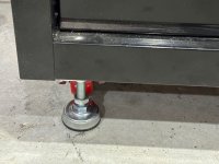
1) Add adjustable legs instead of wheels to toolbox where lathe sits. This really was a nice improvement in stability, rigidity, and adjustability. I found adjustable legs that had the same bolt pattern as my wheels, which made it into a fun little project. I was then really able to dial in and get the work surface level quite easily. After that the lathe was level and the taper was gone.
2) Add 4 jaw independent chuck, This was a whole fiasco in and of itself. I could not find the right chuck with 3 bolt mounting system. So, I bought a 4 bolt version and using my milling machine to drill 3 new bolts holes. But I did not have sufficient y-axis travel. So, I ended up reconfiguring my milling machine and now have the travel back that I lost with Digital Read Out installation. And, I cleaned, lubricated, and adjusted the slides. I wish I had done this years ago. It now works like a dream.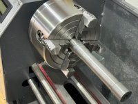
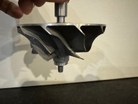
3) I changed my method and tried WBs approach. First I made the concentric outside parts of the shaft. Then, I mounted the 1/4” shaft in the 4 jaw chuck and dialed it in and drilled the shaft hole last. When I rotated it on a dowel pin, I got my best ever extension shaft run out at just about 1.5 thousandths near the tip of the shaft. Lets see if it holds true after I heat shrink it on the motor. This one has some of my best tolerances yet on the 1/4” shaft and 8 mm bearing. They slip fit, but don’t fall off.
If this does not work, then I am going to try to make an extension shaft hole that matches the motor shaft diameter and try WBs glue technique. Another exploration may be using 1/4” precision collet to hold the shaft during the hole drilling operation instead of the 4 jaw chuck.
Here are the next improvements in my journey towards my lathe 101 graduation:
1) Add adjustable legs instead of wheels to toolbox where lathe sits. This really was a nice improvement in stability, rigidity, and adjustability. I found adjustable legs that had the same bolt pattern as my wheels, which made it into a fun little project. I was then really able to dial in and get the work surface level quite easily. After that the lathe was level and the taper was gone.

2) Add 4 jaw independent chuck, This was a whole fiasco in and of itself. I could not find the right chuck with 3 bolt mounting system. So, I bought a 4 bolt version and using my milling machine to drill 3 new bolts holes. But I did not have sufficient y-axis travel. So, I ended up reconfiguring my milling machine and now have the travel back that I lost with Digital Read Out installation. And, I cleaned, lubricated, and adjusted the slides. I wish I had done this years ago. It now works like a dream.

3) I changed my method and tried WBs approach. First I made the concentric outside parts of the shaft. Then, I mounted the 1/4” shaft in the 4 jaw chuck and dialed it in and drilled the shaft hole last. When I rotated it on a dowel pin, I got my best ever extension shaft run out at just about 1.5 thousandths near the tip of the shaft. Lets see if it holds true after I heat shrink it on the motor. This one has some of my best tolerances yet on the 1/4” shaft and 8 mm bearing. They slip fit, but don’t fall off.

If this does not work, then I am going to try to make an extension shaft hole that matches the motor shaft diameter and try WBs glue technique. Another exploration may be using 1/4” precision collet to hold the shaft during the hole drilling operation instead of the 4 jaw chuck.
Last edited:
GTHound
Active member
I heat shrunk the newest shaft and had similar results as before. Went on great with only 10 seconds of heating with torch and a good bond. BUT… runout went from 1.5 to 15 thousandths of an inch now that it is mounted to the motor shaft. Bummer…
Next up grind it off. Then I will try WBs adhesive approach or getting a whole shaft (instead of massive flat area that leaves me with just a little more than a half of a shaft).
Could there be an issue with my heating method? Does a torch work acceptably for heat shrinking or should it try an oven instead for more controlled heating of the shaft?
Last edited:
WB projects
Active member
The oven can in fact be better but your hot rolled stock have a lot of stress.. you may need to rough your part, aneal it then make you final machining. So when you put it back in the oven, all the stress will already be out. Because when you saw your part bend in front of your eyes when removing the tail, it mean you have A LOT of stress
GTHound
Active member
Well after many iterations and chasing my tail, I think I have figured out the root of the problem. I used some decent steel stock and tried WBs method of making the hole last. I used a 1/4” end mill as a boring bar after drilling to 7.75mm since I did not have a small enough boring bar. It worked surprisingly well.
The fit of this iteration was such that sometimes the extension shaft rotated the motor and some times it did not (to be expected, because it was not yet glued). When the extension shaft spun on the motor shaft there was less than a couple of thousandths of run out. What I did not expect was that when the extension shaft rotated the motor I had more than 17 thousandths run out. Bingo! That had been my problem all along.
So the bad news is have a bent motor shaft .The good news is that I have learned a lot, my lathe is set up really well, and I can make good extension shafts.
Not sure how I am going to get a viable motor yet. I will try Castle tomorrow and see if they can help me out.
WB projects
Active member
Well, if really your motor shaft is bend that’s a sad thing! Do you know how could this happen?
If you are ever left with a rotor on the shelf, you can try to make your own motor shaft so you could direct drive your compressor wheel without extension shaft!
If you are ever left with a rotor on the shelf, you can try to make your own motor shaft
GTHound
Active member
My guess is either 1) was bad from the start or 2) there was axial thrust from the compressor and the rotating assembly stopped fast when the compressor contacted the turbo housing. I cant really recall as it was a while ago and did not seem catastrophic at the time but rather a metallic squeal and it was stopped immediately.Do you know how could this happen?
Great minds think alike! That is precisely what I have been pondering. Somehow removing the steel shaft from the magnet portion and making my own shaft with no extension.If you are ever left with a rotor on the shelf, you can try to make your own motor shaftso you could direct drive your compressor wheel without extension shaft!
I may try Matnrach’s approach first where I would cut off the flat part (which seems to be the bent part) of the shaft and inboard the extension shaft and add a larger bearing size.
If that doesn’t work, I would love to press a new steel shaft into my current magnet array on and rotor. My hunch is that the easy way to get the shaft out would be heat. But I would be concerned about the heat demagnetizing the neodymium magnets I may just have to try pressure, but my hunch is that may shatter the magnet array.
Last edited:
WB projects
Active member
I did try with my TP motor and it was glued and pressed. They scuffed the surface of the shaft so the glue can stick. I did pull the shaft out with a press.My hunch is that the easy way to get the shaft out would be heat. But I would be concerned about the heat demagnetizing the neodymium magnets I may just have to try pressure, but my hunch is that may shatter the magnet array.
GTHound
Active member
In response to my bent motor shaft. I have decided to go into slice and dice mode, since I really don’t have much to lose as it is sunk cost. So, I took the rotor out of the motor to investigate further. I 3D printed a plastic sleeve and slipped it over the magnets to protect them. Then I dial indicated it in on the lathe using the 4 jaw chuck. I used the outside diameter of the front edge of the magnet housing as an indicating surface.
Then, I designed and 3D printed a holder for my Dremel tool so that I could attach it to my lathe tool post. I then cut off about 17mm of the shaft (the most bent part) with a cut off wheel.
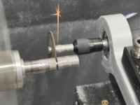
That leaves me with about 20 mm of motor shaft to grip with the extension shaft. That said, I will also get a bigger bearing ID like matnrach did that rides on the outside of the extension shaft, but inside the motor housing. I like this idea for serval reasons. 1) only 2 bearings, 2) shorter shaft, and 3) I can design the shaft to prevent end float, due to the bearing orientation.
I believe end float has been a key problem for me. Even at 6 PSI x 8 sq inches x 50% force vector = ~ 24 pounds of axial force on a motor not design for axial force.
Next I blued up what was left of the shaft and put a stone on the dremel tool and made quite a few passes of less than 0.001” each. The pictures below are taken at the same time but from different angles, which shows that the shaft was indeed bent.I am slowly getting the shaft back into concentricity.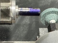
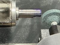
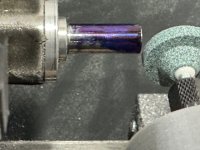
After taking all of the blue off, everything was trued up and concentric around the shaft. And everything is straight (cylindrical?) as I moved the indicator up and down the carriage along the shaft, so the shaft is not cone shaped. Here is the after pic, I don’t have a before pic. The shortened and straightened shaft is on the left hand side.
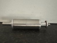
The refurbished shaft is too short to use the original design.
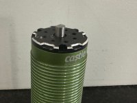
But should be able to attach further inside the motor housing.
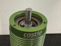
The new diameter is 0.7777mm.
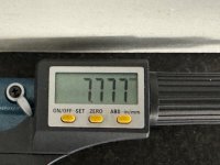
So I have removed about 8-7.777= 0.223mm or a little less than 9 thousandths of an inch. But now it runs true. Now I just need to figure out how to make a hole that size in a new extension shaft to receive it.
And I need to redesign my extension shaft and motor mount system to accommodate the new dimensions and bearing layout. I may even completely get rid of the factory motor end cap. I will have to do some design work and see. At least for now, I am unstuck and have a direction to explore.
Then, I designed and 3D printed a holder for my Dremel tool so that I could attach it to my lathe tool post. I then cut off about 17mm of the shaft (the most bent part) with a cut off wheel.

That leaves me with about 20 mm of motor shaft to grip with the extension shaft. That said, I will also get a bigger bearing ID like matnrach did that rides on the outside of the extension shaft, but inside the motor housing. I like this idea for serval reasons. 1) only 2 bearings, 2) shorter shaft, and 3) I can design the shaft to prevent end float, due to the bearing orientation.
I believe end float has been a key problem for me. Even at 6 PSI x 8 sq inches x 50% force vector = ~ 24 pounds of axial force on a motor not design for axial force.
Next I blued up what was left of the shaft and put a stone on the dremel tool and made quite a few passes of less than 0.001” each. The pictures below are taken at the same time but from different angles, which shows that the shaft was indeed bent.I am slowly getting the shaft back into concentricity.


After taking all of the blue off, everything was trued up and concentric around the shaft. And everything is straight (cylindrical?) as I moved the indicator up and down the carriage along the shaft, so the shaft is not cone shaped. Here is the after pic, I don’t have a before pic. The shortened and straightened shaft is on the left hand side.

The refurbished shaft is too short to use the original design.

But should be able to attach further inside the motor housing.

The new diameter is 0.7777mm.

So I have removed about 8-7.777= 0.223mm or a little less than 9 thousandths of an inch. But now it runs true. Now I just need to figure out how to make a hole that size in a new extension shaft to receive it.
And I need to redesign my extension shaft and motor mount system to accommodate the new dimensions and bearing layout. I may even completely get rid of the factory motor end cap. I will have to do some design work and see. At least for now, I am unstuck and have a direction to explore.
Last edited:
WB projects
Active member
Remember the bore with an endmill tips I gave youNow I just need to figure out how to make a hole that size in a new extension shaft to receive it.
GTHound
Active member
I do like that tip and actually leave a 1/4" end mill in one of my lathe tool holders. I think I still struggle with the dimensions as I can't seem to get a good inside diameter measurement on small holes. And once I do I am relying on lathe micrometers, which aren't bad. Maybe I just need to set up a dial indicator to measure cross slide position. Or, maybe I just need to bite the bullet and get a DRO kit for my lathe.Remember the bore with an endmill tips I gave you
GTHound
Active member
I was pondering some way to mathematically represent the overhang of different extension shaft configurations for comparison. I landed on the ratio of the outboard shaft extension (beyond the end bearing) to inboard shaft (supported between bearings).
Below are 3 configurations, the first of which is the standard castle 1721 motor with no extension shaft. They usually just mount a pinion gear on the end of the shaft for RC car use.
0) Standard Castle 1721 motor: 29% overhang
Below are 3 configurations, the first of which is the standard castle 1721 motor with no extension shaft. They usually just mount a pinion gear on the end of the shaft for RC car use.
0) Standard Castle 1721 motor: 29% overhang
- Bearing to bearing support = 91 mm
- Shaft beyond bearing = 26 mm
- Extension Ratio = 26 / 91 = 29%
- Bearing to bearing support = 91 mm
- Shaft beyond bearing = 93 mm
- Extension Ratio = 93 / 91 = 102%
- Comment: I have had issues at this length, thus inspiration to shorten
- Bearing to bearing support = 106 mm
- Shaft beyond bearing = 54mm
- Extension Ratio = 45 / 91 = 51%
- My V1 design had over 3X the stick out of a standard castle motor.
- My V2 design minimizes unsupported shaft length and reduced overhang by 50%
- Version 2 above which I am currently engineering/refining reduced stick-out by moving bearing outward (outside the motor can) and by shortening the shaft by moving the slip fit inside the motor can.
- The combination shortens the shaft enough to eliminate the hub spacer as Matnrach pointed out with a little bit thicker backplate.
- I may try a plastic backplate again, or may cast and machine a new one out of aluminum (printed mold last night).
Last edited:
GTHound
Active member
In hopeful (naive? misplaced?) expectations of a making a viable extension shaft, I have decided that I will plan to balance the whole rotating assembly. So, to that end, I did a quick design and print of a shaft balancing apparatus. It holds the shaft assembly up at the ends in super low friction bearings and allows the heavy part rotates to the bottom. I will then either grind weight off of the bottom or add balance compound on top. Here is a picture of my prototype balancing rig with the whole rotating assembly; motor rotor and extension shaft (prototype) with compressor wheel and nut.
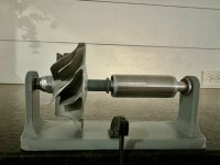
One thing I noticed was that despite the tight fit of the 3D printed extension shaft, it was quite wobbly and off axis. My idea of the day is to extend the extension shaft bore another 1 mm and have it press up against the end of the motor rotor. This surface should be square with the rotor and may help square up the extension shaft and get things back concentric / cylindrical with each other.
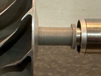
Here is a picture of the deeper bore and chamfered extension shaft so that it butts up tight against the rotor magnet housing. I was amazed at the difference it made in getting everything on the same axis. I could even go to a deeper or wider surface contact. If it helps in plastic, my hope is that it will also help when I make the new design in metal.
Another idea I had now that I see the whole rotating assembly is to attached the extension shaft to the motor rotor before machining the final dimensioning of the 1/4” compressor shaft and threads.
That my friends is the power of prototyping. I keep discovering things that I did not anticipate.

One thing I noticed was that despite the tight fit of the 3D printed extension shaft, it was quite wobbly and off axis. My idea of the day is to extend the extension shaft bore another 1 mm and have it press up against the end of the motor rotor. This surface should be square with the rotor and may help square up the extension shaft and get things back concentric / cylindrical with each other.
Here is a picture of the deeper bore and chamfered extension shaft so that it butts up tight against the rotor magnet housing. I was amazed at the difference it made in getting everything on the same axis. I could even go to a deeper or wider surface contact. If it helps in plastic, my hope is that it will also help when I make the new design in metal.

Another idea I had now that I see the whole rotating assembly is to attached the extension shaft to the motor rotor before machining the final dimensioning of the 1/4” compressor shaft and threads.
That my friends is the power of prototyping. I keep discovering things that I did not anticipate.
Last edited:
GTHound
Active member
I think that I may have a viable extension shaft!
I am basically using a modification of Matnrachs design with extension shaft attaching inside the motor housing and WBs manufacturing approach. The key was to make the hole last and use a 1/4” end mill mounted in my tool post as a boring bar. It was quite easy to keep the hole cylindrical with this method. Every tick on my cross slide micrometer is supposed to be 0.05 mm and sure enough every time I turned it in 2 ticks the hole got 0.1 mm bigger. I took 0.1 mm steps from 6.7mm to 7.7mm to get the feel of it and did a couple of spring passes at the end. The tricky part is that I don’t have a great way to measure small inside bore diameters.
When I put the extension shaft and rotor in my balancing jig it spun freely and most important axially even though it is not yet pushed on completely. Now I need to see if I can press on the rest of the way and apply some wicking adhesive.
Balanced in this scenario is defined as the rotor stays in any position it is placed.
I starting sticking on little steel nuts on the light side of the magnetic rotor (the heavy part rotates down, so the light side is the top). It took 10 nuts to balance the assembly. It is amazing how long it rotates once it is balanced.
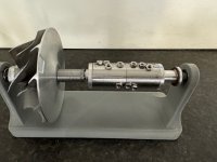
The total weight I need to add or remove (depending on how you look at it is 3.1 grams).
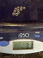
Now I need to see if I can find clever places to remove 3 grams of material from the rotating assembly with the dremel tool.
I am basically using a modification of Matnrachs design with extension shaft attaching inside the motor housing and WBs manufacturing approach. The key was to make the hole last and use a 1/4” end mill mounted in my tool post as a boring bar. It was quite easy to keep the hole cylindrical with this method. Every tick on my cross slide micrometer is supposed to be 0.05 mm and sure enough every time I turned it in 2 ticks the hole got 0.1 mm bigger. I took 0.1 mm steps from 6.7mm to 7.7mm to get the feel of it and did a couple of spring passes at the end. The tricky part is that I don’t have a great way to measure small inside bore diameters.
When I put the extension shaft and rotor in my balancing jig it spun freely and most important axially even though it is not yet pushed on completely. Now I need to see if I can press on the rest of the way and apply some wicking adhesive.
Balanced in this scenario is defined as the rotor stays in any position it is placed.
I starting sticking on little steel nuts on the light side of the magnetic rotor (the heavy part rotates down, so the light side is the top). It took 10 nuts to balance the assembly. It is amazing how long it rotates once it is balanced.

The total weight I need to add or remove (depending on how you look at it is 3.1 grams).

Now I need to see if I can find clever places to remove 3 grams of material from the rotating assembly with the dremel tool.
Last edited:
WB projects
Active member
For mesuring your inside hole, you can make go/no-go pin! If you want your hole between *for example* 8 and 8.05mm you can make a go pin 7.98mm and a no-go of 8.05mm
WB projects
Active member
don’t know the best way to balance your assembly! Maybe remove on the compressor wheel? Since is bigger, you may remove less?
