2L Opel GT e-boost build

If the motor produces 6kw it wont dissipate 6kw of heat, more likely around 600w which is 90% efficiency
Thank you marnrach. Here is an update .

If I pull ~ 190 amps @ 32Volts that is about 6,000 watts. 6,000 watts x (100-85% motor efficiency) = 900 watts x 10 seconds = 9,000 joules.

If I have a half liter of water as coolant 500g x 4 J/g degrees C= 2,000 joules per degree C thermal capacity. So, if I get could 70% of the heat to go into the water, the water would increase 70% * 9,000 joules / 2,000 joules per degrees C = 3 degrees C per hit.

That seems more reasonable.
 
Last edited:
Thank you marnrach. Here is an update .

If I pull ~ 190 amps @ 32Volts that is about 6,000 watts. 6,000 watts x (100-85% motor efficiency) = 900 watts x 10 seconds = 9,000 joules.

If I have a half liter of water as coolant 500g x 4 J/g degrees C= 2,000 joules per degree C thermal capacity. So, if I get could 70% of the heat to go into the water, the water would increase 70% * 9,000 joules / 2,000 joules per degrees C = 3 degrees C per hit.

That seems more reasonable.
Which is why those heat sinks work well and are much simpler however the body of the motor needs to be smooth for max heat transfer. I was originally going to go down the water cooling route as I have a charge cooling circuit already in the car but tried the heat sink first as it was way simpler.
 
Last edited:
OMG I am so pissed right now. @GTHound your data look way better then me.
I’ve done my first test with my new motor and I am super disappointed. Like REALLYY disappointed. Something wrong with my brand new refurbished MGM x2 controller. I’ve been waiting for 11 months for this and I think I will need to send this back 😤
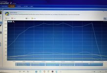
The data I have make apsolutly no sens. IMG_3025.jpegHope you can this this clearly!
I hit the ESC cut off at only 40k rpm.
In this graph, I was running the impeller with not compressor housing trying to find what’s go wrong. With or without compressor housing, it’s almost the same thing. 2100watts 400A « pulse current » (cut off at 800A) but only 60A in the input ESC ?! WTF do you see what’s makes no sense? Btw I have plenty of voltage.
 
OMG I am so pissed right now. @GTHound your data look way better then me.
I’ve done my first test with my new motor and I am super disappointed. Like REALLYY disappointed. Something wrong with my brand new refurbished MGM x2 controller. I’ve been waiting for 11 months for this and I think I will need to send this back 😤
The data I have make apsolutly no sens. View attachment 719Hope you can this this clearly!
I hit the ESC cut off at only 40k rpm.
In this graph, I was running the impeller with not compressor housing trying to find what’s go wrong. With or without compressor housing, it’s almost the same thing. 2100watts 400A « pulse current » (cut off at 800A) but only 60A in the input ESC ?! WTF do you see what’s makes no sense? Btw I have plenty of voltage.
Ohh, how disappointing… I feel for you.

At least you are an amazing machinist and have that piece working for you.

Here’s to Finding A Way to a viable electric super charger for our power and torque hungry 4 cylinder engines.
 
Last edited:
Updates on 2 fronts: 1) shrink fit shaft, 2) cooling system

1) I have been struggling to make my shrink fit extension shaft. I just can’t seem to make the hole small enough for a 20ish micron interference fit. After each iteration I am consistently disappointed when the motor shaft slips inside.

Here is what I have been learning / doing to make an interference fit.
  1. Precision aligned tailstock to headstock on lathe
  2. Got new sharp cobalt drill bits
  3. Put 0.3140” reamer in reverse and stone honed end at 45 degree angle
  4. Switched to light weight oil (WD-40 vs Tap Magic)
  5. Moved to smaller pilot hole. Even a good 5/16” drill makes a bigger hole than the drill 5/16=0.3125”, so switching to a 19/64 = 0.297” drill.
  6. Chamfer hole before reaming
  7. Ream super slow rpm with high feed
  8. Stop lathe before withdrawing reamer
I have made progress with my half a dozen practice holes today. Getting tighter and tighter. One thing that may help is a new sharp 19/32 drill bit that should show up tomorrow which is roughly 0.015” smaller than the reamer. If that doesn’t work, I am going to have to find a differ reamer that is a 0.3130” or 0.3135” since the hole is larger than the reamer. However, I hope I can get there with sharper drills, better technique, lighter weight oil, and mods to my existing reamer.

2) progress on water cooling

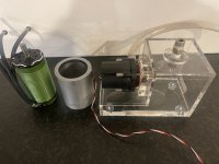
I have fabricated a water jacket to slide over the castle 1721 motor. And have a cooling reservoir and pump. Just need to get the shrink fit shaft figured out to be able to test it. IMG_1147.jpeg
 
Last edited:
one quick question, do you put any timing to your motor?
I do not put any timing in my electric motor (it spools up plenty fast). In fact, I have taken timing out for slowest ramp up setting and ramp it even slower than that with my arduino microcontroller .

I am planning to take ignition timing out of my fuel injection algorithm as a function of boost.
 
For the timing castle motor recommend 0 and that’s what I did but I was just wondering what cause this weird datalog. Anyway I get in totch with Joe from castle creation, really nice guy and we all conclude that my ESC is still broken..
Anyway.
@GTHound did you see my video when I explain how to do my shrink fit? You will NEVER get constant results with reamer or drill. I use a endmill like a boring bar! Suuuuper easy to get the perfect fit!
BTW I not recommend to do a shrink fit on a keyed shaft. Thats s reason why I will do a new shaft tomorrow! Because when the shaft shrink, it look like the shaft bend over the flat spot on the shaft! I will go back to a pretty snug fit with green loktite! It’s able to cover a gap up to 0.010" and super strong (don’t remember the PSI of toughness)
If you are patient enough and if you are interested too, I will make a video how to make a perfect shaft no matter what. I did cut some corner in the past but I will do the perfect way tomorrow!
 
I really don't understand your difficulties. As for drilling and reaming, of course you can get perfect results if you use correct sized drills and reamers. The final dill needs to be around 0.1mm less than the reamer nom size. I have found drilling the hole be very progressively gives best result.
Also I have not found an issue shrinking onto a shaft with a small flat. In fact you need it to let the air out as you shrink it on
 
OMG I am so pissed right now. @GTHound your data look way better then me.
I’ve done my first test with my new motor and I am super disappointed. Like REALLYY disappointed. Something wrong with my brand new refurbished MGM x2 controller. I’ve been waiting for 11 months for this and I think I will need to send this back 😤
The data I have make apsolutly no sens. View attachment 719Hope you can this this clearly!
I hit the ESC cut off at only 40k rpm.
In this graph, I was running the impeller with not compressor housing trying to find what’s go wrong. With or without compressor housing, it’s almost the same thing. 2100watts 400A « pulse current » (cut off at 800A) but only 60A in the input ESC ?! WTF do you see what’s makes no sense? Btw I have plenty of voltage.
WB, I wonder if there could be a problem with the configuration in the ESC regarding the number of poles, etc.
I really don't understand your difficulties. As for drilling and reaming, of course you can get perfect results if you use correct sized drills and reamers. The final dill needs to be around 0.1mm less than the reamer nom size. I have found drilling the hole be very progressively gives best result.
I am now able to reproduce consistent sized holes with a nice wall finish albeit the same size of the shaft.

I consistently get a measurement of the motor shaft of 0.3146” with my outside micrometer.

But the flute to flute measurements across one of the dimensions of my 6 flute 0.3140” reamer is larger than the others and consistently 0.3145”. Bingo! It doesn’t get down to 0.3140” until about halfway up the reamer as they are taper in nature.

It sure seems to me that the reamer is out of spec or my micrometer is out of calibration.

If the reamer is measuring 0.0005” oversized x 25.4 x 1000 = 12.7 microns. Which is just about how much I want to undersize the hole for the interference fit.

So if I just had the proper sized reamer that I ordered, I should be in business. I need to either 1) modify the reamer so that it drills smaller holes for the 10-15 micron interference fit or 2) return / exchange the reamer for another that is dimensioned to specification plus or minus a thousandth of an inch.
 
Last edited:
I ordered and received another 0.3140” reamer from the same manufacturer. This one is just a few tenths over and has a tapered 45 bevel on the front of the reamer. Perhaps on the last one they missed the finishing and quality control steps. I guess i just had a bad reamer tool. So I will return the problematic reamer.

The new one worked great on some test aluminum. So, now I can forge ahead with making the new steel shrink fit extension shaft and see what kind of tolerances I get with my concentricity.
 
Hello, i know i'm late to the game on your thread but oil no longer an issue with the turbo? I have 2 gt28s that are laying around and one would make for a perfect donor for the eturbo project. However I see you had to forge your own adapter for the backside? Is there a different base that is an option to go with?
 
oil no longer an issue with the turbo?
I have not had an e-turbo on my car yet. But here is what I know.
  1. No heat coming in from contact with exhaust
  2. No heat coming in from constant boost (only when spooked up)
  3. ABEC 5 (I believe but would have to check my notes) Bearing provided by e-turbo motor.
  4. I added a secondary bearing more as a stabilizer to complement the motor bearing.
  5. A engineer friend of mine had suggested keeping the oil bearing that came with the turbo.
I see you had to forge your own adapter for the backside? Is there a different base that is an option to go with?
  • I have not found anything off the shelf ready to go other than a super charger. But the ones I was looking at were pricey.
  • I could have just bought a chunk of aluminum, but forging was more cost effective for me. Plus, it is fun to melt aluminum
  • I required a custom design for my bearing, spacing, etc.
  • may be able to get by with 3D printing with the right design and materials. All of my early bench work was just 3D printed.
 
Well, it has been a long time since I have posted. I have learned a lot about and advanced my capabilities on the lathe, made a lot of extension shafts. I have learned a lot about machining and measuring concentricity. I have systematically eliminated one problem at a time, but still don’t have a viable extension shaft for my eturbo motor.

I think I have tried over a dozen metal extension shafts, all of which were fails. Below is a picture of a fair representation of the iterations.
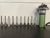
IMG_2446.jpeg

Starting on the left was 3D printed ABS. Very concentric, spun up nicely, but only good for a short life and basement experiments and design work. Then I tried getting a laser sintered shaft, which was plenty strong, not concentric enough (they printed it horizontal and it dropped).

3rd in, I tried using the 1/4” shaft that came with the turbo with 1/4” to 8mm adaptor. The challenge I had was the coupler was not concentric or balanced enough.

4th in, a friend made a steel shaft on his lathe for me. The shaft is amazingly concentric with less than a thousandth run out. But it got wonky with the set screw attachment to the motor shaft.

Then I got my own lathe (nice complement to my milling machine) and have been learning over the last few months (good choice for me as I am learning driven and build lots of car parts). The next few shafts had poor tolerances for the 1/4” shaft and 6 mm bearing and or shrink fit. So they never were tried with the motor.

At first it was hard to get the precision for the shrink fit. But once you have the right tools, setup, procedure, and technique, it is quite easy and repeatable.

All I do is drill with a center drill, then increasing drill sizes up to 7.75 mm and finish up with 0.3035” reamer. The shaft is 7.98 mm = 0.3242”. So the hole is roughly 0.0007” smaller than the shaft at room temp or about 18 microns. Once the shaft is complete I heat it up with the torch for 15-20 seconds and it slides right onto the motor shaft. Once it cools down, the only way I can get extension shaft off of the motor is to cut it off (which I have done too many times).

I eventually abandoned turning the shaft in lathe chuck and have been turning between centers to improve concentricity. The last shaft I made (perhaps my 10th or so out of steel) was concentric to ~ 1 thousandth of an inch. However, after heat shrinking it onto the motor the shaft runout went to about 14 thousandths of an inch. Arghh (again). I have not spun this one up beyond 2 psi due to vibration.

My hypothesis is that there is a lot of force or weird cooling at the flat spot on the shaft causing the deformation during heat shrinking. I have taken many a good shaft and destroyed the concentricity with heat shrinking it onto a shaft with a flat spot. If that is the case, my motor is probably not viable for my application. If that is not it, perhaps my motor rotor itself has poor concentricity (again not viable).

Next steps:
  1. Cut off current extension shaft from motor
  2. Measure concentricity of motor rotor
  3. Turn a pin in lathe to motor shaft specs and heat shrink a shaft onto it and check concentricity (this will test above hypothesis)
  4. Call Castle and see if they will send to me a rotor for my motor without a flat spot.
Let me know if you any other thoughts…

Too bad as I was excited for a usable shaft. It was highly concentric (before heat shrinking) and had even balanced my rotating assembly.
 
Last edited:
I presume the bore is drilled and reamed WITHOUT removing it from the lathe i.e the bore is machined in the same setting as the shaft where the compressor wheel is mounted. I have successfully mounted an extension shaft on a motor with a flat on. In fact you do need a slight flat on the shaft to allow the air out as it is shrunk onto the motor.
Also I assume you have seen my last version in which I modified the rotor of the motor so that only bearing is the one in the motor casing top cover (a new larger bore bearing was required) This minimises any unsupported shaft length and also prevents any misalignment issues between the motor bearing and a bearing in the backplate.
 
Last edited:
Thank you for the thoughtful reply.
I presume the bore is drilled and reamed WITHOUT removing it from the lathe i.e the bore is machined in the same setting as the shaft where the compressor wheel is mounted. I have successfully mounted an extension shaft on a motor with a flat on. In fact you do need a slight flat on the shaft to allow the air out as it is shrunk onto the motor.
Yes, correct, all operations are made without removing from the lathe, or most recently between centers (which is repeatable concentric).
I have successfully mounted an extension shaft on a motor with a flat on. In fact you do need a slight flat on the shaft to allow the air out as it is shrunk onto the motor.
Ahh, thank you for sharing that. Well that takes care of that hypothesis. So something else is going wrong.

Also I assume you have seen my last version in which I modified the rotor of the motor so that only bearing is the one in the motor casing top cover (a new larger bore bearing was required) This minimises any unsupported shaft length and also prevents any misalignment issues between the motor bearing and a bearing in the backplate.
I will go back and study this. Thank you for the reminder. I currently do have a 3 bearing design (2 in motor) and one outboard for shaft support. My bearings seem aligned, but it is hard to measure.

I like the idea of minimizing the extension shaft length as the longer shaft amplifies the runout. I do have a nice high speed ceramic bearing from Boca Bearings. A redesign may be in order.
 
I have a completly different opinion than matnrach. I do believe the flat spot a problem for the heat shrink. Try a test with a shaft with no flat like you said and I think it will be fine. I had the exact same issues when shrink fit on the shaft.
I do think drill and ream is not the solution for concentric hole. Yes you have a precise hole but I believe it’s not the solution for concentric hole. Yes you can slowly increase drill and get a better chance but I don’t beleive to be the best solution.
If you want to make an other test to see what is the best solution, I do believe you should try what I did on mine. Do you remember the procedure I did? Try a smaller fit and glue the shaft instead of shrink fit! Green locktite!
 
Top