What batteries are you using?

I'm really eager to see how those cells work out - please keep us posted. My own experience tells me that until you put the compressor on the engine, you won't know how fast the motor will actually turn - not one motor I've tried has been able to hit it's rated kv in actual use, though some were closer than others. I'd start with testing with the compressor wide open - that'll put the heaviest load on it and limit the rpm to a lower level than it'll likely be on your engine. Just my two cents.
Ahh, that is good advice and makes sense now that I think about it. First of all, I am still working on the mechanical coupling of the motor and compressor, so I like the idea of limiting the RPMs a bit. This will give the electrical system (motor, ESC, and batteries) a harder work out while I gain confidence in the mechanical side of things.

I think what that means is that I can set my “snorkus” aside. I just 3D printed mine out of TPU. I appreciated the practical bench testing advice. So, there is no issue building pressure wide open?

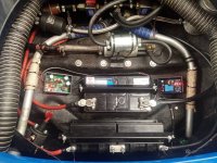
My BMS is passive and doesn’t have any LEDs or anything. So I didn’t think that my battery management system was working. But after sitting for 10 days the whole system was at 3.333 volts. One cell had 3.332 and one had 3.334. But it does indeed work to balance the cells.
 
Here is a pic of the assembled battery array.

IMG_9999.jpeg
And here is a chart of a Data log from an early pull while my shaft assembly was still working. I got it up to about 45K RPMs at 39% throttle and somewhere over 2 PSI with my version of the Snorkus. Volts dropped from 39 to 33 and I pulled about 71 amps.
IMG_9974.jpeg
 
Last edited:
Sorry about taking so long to respond. They poured my foundation incorrectly in Texas, and dealing with that from over 1,600 miles away is extremely difficult and frustrating; I'm also packing up stuff from my house for my next trip down. I can't wait until all this other stuff is in the rearview mirror and I can really focus on this stuff.

It looks like you ran your setup for quite some time - which is great. But what I'm a little concerned about is the voltage drop under relatively light load. Run it wide open (no snorkus) and see what happens - the compressor will go into choke, rpm will be less and current draw will go way up.

Overall though, your setup looks pretty stable, which is good given that you're spinning pretty fast. I'd do at least a 2p setup on those cells if possible; maybe 3p or 4p if feasible. Though in all honesty, 2 SMC drag packs would do wonders for you - like the ones I tested here:


I'd love to see the datalog running wide open for comparison sake. Please give that a try and post it - the information would be very useful to see if my results translate directly to other setups (I think they will, but until someone tries it, we can't be 100% sure).
 
Thanks for the reply. I am away on vacation now. But, I have a friend who machined a shaft coupler on his lathe with surprisingly low run out. He shipped it to me and I hope to test it when I get home. That had been my limiter. Hopefully I can spool it up and do the choke test without the Snorkus per your suggestion.

I actually added a few extra battery cells (running 12S 2P) instead of 10S or 11S that I thought I would need to get to 33.6 volts maximum of the motor. It just looks better and has a better bus bar layout as the case was designed for 24 cells, albeit 4S6P. So, I am actually counting on a little bit of voltage drop to stay in range. With no voltage drop 10 cells would be just about right 3.3 volts x 10 = 33. With 11 cells in series I will be at 11 x 3.3 volts = 36.3, so that would handle 36.3-33.6= 2.7 voltage drop. I would need roughly 12 x 3.3 = 39.6 volts - target of 33.6 or 6 volt drop to handle the 12S LiFePO4 array. I know this is sort of backwards thinking.

That said it seems like that 6 volt drop is roughly what happened in my short run (a drop down to 33 volts from 39 volts). So that is roughly a 6/39= 15% drop. I see your concern as this was only at 70ish amp run and the voltage drop looks precipitous with no apparent end in sight. We shall find out as we go for more boost. Perhaps that is what I get for buying cheapo $5 used cells.

So, what would it cost me to try the SMC drag packs? Seems that they are 7.4 volts and $115 each. So, if my target is 33.6 volts. 33.6 / 7.4 volts per pack = 4.5 packs. So it seems it would be a $500 experiment. Sounds like a good way to go for low voltage drop but a bit too pricey for my blood at this stage in the game.
Let me know if there is a different variety to consider.

Lastly, is there a way to determine is I have a few bad cells that are spoiling the bunch and causing my rather substantial voltage drop? Would it work to test individual Cell voltage After a hard pull and look for the low ones?

On another forum I found this about headway cells “Headway 38120s are about 5-6mOhm and they are known for being 'saggy'”. So, they might just not be a good choice for our e turbo application, which i is what you were poking at. Time will tell.
 
Last edited:
I think you're pretty much spot on with everything. Running more cells than necessary has two advantages and two primary disadvantages. The advantages are that you can compensate for voltage drop. The other advantage is you don't have to charge them all the way - if you look at a typical lithium discharge curve, you'll see a big drop initially, and then from like 80% soc to about 30% soc, it's pretty flat, so your performance is more consistent. The two disadvantages are additional pack size and weight and you're adding a little more internal resistance because of the additional cells.

Checking the cell voltages after some heavy drain is probably the best way to identify weaker cells - better than IR measurements even,because that's a real-world test. If I did the SMC packs, I'd get the biggest (i.e. most cells, highest voltage) ones I could get, because wiring between packs is a source of loss. But start with what you have. If you monitor voltage at the pack and compare it with what you're seeing at the ESC, then you can see what kind of losses you have in the cabling.

I'd go ahead with what you've got and you seem to have a very good grasp of what's going on and what's needed, so I think you're in a good place.
 
I did not particularly want LiPo in my car so went down the route of 2 12v AGM motorcycle batteries. The application is for my twincharger so it is only used as anti-lag with a relatively small power demand and not constant boost. It is sized for my application but has on board charging with a step up converter and charging modulation circuit. The batteries can supply 280CCA so at normal operating temperature it can supply way more. The only downside is weight which is around 7kg but much simpler and I have to say it works faultlessly. However the car is extremely light and since the engine is mid mounted the extra front weight is arguably of benefit. (pictured without covers on the control boxes)
 

Attachments

  • IMG_20230415_161358 (1).jpg
    IMG_20230415_161358 (1).jpg
    396.4 KB · Views: 14
Last edited:
start with what you have.
Thanks for the reply Alex. I like your thinking. We will see how far I can get with my sub $200 budget battery.

A friend of mine made a mild steel adaptor shaft to go between the motor and compressor. So, I am back in business (the business of doing experiments that is). I am still working on getting a viable setup, but was able to get something up and running today and gathered a bit more data. It truly is scary to ramp this thing up. That said, I got to 3 PSI today before the restrictor (aka the Snorkus) blew off.

Below is a snippet of the data log from the aforementioned run. At 3 PSI, throttle was at 47%, RPMs were at 40K. My battery voltage is pretty saggy and dropped to 30.4 at 108A. That multiplies out to 3,200 watts / 746 watts per HP or 4.4 HP.
IMG_0440.jpeg

I must admit, I am still running some way too low of gauge wires (albeit only 18 long) from the battery to the ESC. They are getting warm and may be contributing to my voltage drop. I have ordered / received some more permanent parts (4 gauge battery wires and Anderson connector). I hope this was the weak link and helps reduce the voltage drop under heavy loads.

That said, I am surprised with how fast the battery voltage rebounded. Below is a little slice at the tail end of the run. You can see the voltage rebound from 30V to 38V in less than half of a second (17.3 seconds to 17.8 seconds on the time scale).
IMG_0441.jpeg
 
You can see that the voltage drop is inversely proportional to the amps. I don't know what gauge your wires are but an 8 volty drop would be way too much for 8 gauge wires. Maybe there are poor soldered connections or bad plug in connectors that are causing the excessive voltage drop.
 
GTHound - you can start taking voltage measurements at various parts of the battery during a run and comparing it with what the ESC is seeing. Like 88fiero says, you may have a bad connection somewhere. Even if you're only using 8 gauge wires (for example), at 18 inches long, you'd still see less than 1% voltage drop.

edit - n.m on the rest of my message, I just saw you posted an update in the projects section.
 
Hi Guys,
I'm still torn on the battery a little and trying to decide which way to go. The more i think about the charging, storage time, readiness and fire risk the more i'm leaning away from lithium based batteries for my application.
Is the main reason for not using automotive batteries the weight? It seems they'd be much easier to manage and cheaper for comparable capacity.
The performance hit for the weight doesn't seem too bad. I'd be looking at 235HP/T vs 250HP/t which i don't think would be terribly noticeable for the simplicity of it? what am i missing?
 
For lead/acid batteries, the shape of their discharge curve is terrible, as is the life. Plus they have a pretty poor internal resistance for their weight. Can they be made to work? Yes. Are they worth using? No, not in my opinion.

Lithium battery types pros/cons:

LTO cells are the safest, fastest to charge, have literally 100 times the life of lead acid, and the lowest resistance. They also work well in temperature extremes. However, they aren't terribly cheap or power dense (though far more power dense than lead/acid).

LiFePo4 - second safest, have the most logical voltage range for automotive use, are the second most power dense, have 10 times the life of lead acid, do the second best in extreme temps, have fairly low internal resistance, are becoming cheaper and much more prevalent. They also have an extremely flat dishcarge curve. The only real downside is they're not the most power dense, though more so than LTO.

LiPo (NMC, etc) - The most power dense, and probably the cheapest (though, amp hour for amp hour, LiFePo4 might beat them now). They have fairly low internal resistance and a fairly flat discharge curve. They can also be pretty affordable. However, they are also the most dangerous, have the shortest lifespan (only about 4-5 times that of lead acid) and don't do well in temperature extremes.

At this point in time, LiFePo4 are probably the best option for most cases. I'm using LTOs because I have them. If I didn't, and I was looking for compactness, I'd use SMC drag racing packs (LiPos) - though I'd put them in a safe housing of some sort (steel sheet metal box). Otherwise, I'd use LiFePo4 batteries.
 
Here's a sample discharge curve, fwiw:
Discharge-curve.jpg
 
In my case which is a twincharged application, the duty cycle is very low and the SOC of the 2 series AGM batteries are always close to 100%. This is why I chose them. They were also easy to maintain and charge. I could be wrong of course but for me they seem work fine.
 
I get it… The battery is a big deal. I was stuck there too. In fact until I found the solution below, I thought this project was going to be a no go for me due to battery cost. I was also considering using 1/4 of a Prius battery (200 volts / 4 = 50 volts). But found the budget build outlined below.

I bought all of the components for my LiFePO4 battery pack for less than $200 after tax delivered. My decision was driven by the factors Alex outlined above: a combination of performance, safety (less fire risk than Lithium Polymer), and affordability. Plus I considered the whole fabrication / build and final package.

My battery pack is a 24 cell 12S2P configuration and about the size of typical car battery. It is made from used Headway 38120 HP 3.2V 8AH LIFEPO4 battery cells.

It was a fun build. I like the screw together approach. I was in a hurry and did some quick cuts on the bus bars (originally designed for 4S6P to replace a 12 volt car battery). I meant to mill straighter wider gaps in the buss bars and may do that when I go to add my anti corrosion compound.

IMG_0494.jpeg
All the components came from the battery hook up with fast delivery (from this country) and consolidated in one box to minimize shipping cost. I have only charged the battery pack once since the initial to charge and have 97 data logs from experimental runs of my electric supercharger in the basement. I am going to order my step up transformer today and try charging it with that from a 14.3 volt source (to mimic my alternators output).

I really like the package (the holder was only $15, and came with solid copper buss bars). I was going to cut off the handles on the top, but decided to keep them for easy lifting out of the engine bay and made some custom shelves for electronic component mounting (ESC, BMS, micro controller, step up transformer, etc).
IMG_0534.jpegIMG_0538.jpeg

The only downside I have found so far is that the voltage is a bit saggy. Drops from about 39 volts to about 30 volts under a 200 AMP load when the battery needs to be charged. Not sure if it would be better with new vs used headway cells or if it is the design of the headway cells in general. But that has not been an issue for me, I am getting the watts that I need to achieve my design goals and have heavy duty components.that said, I haven’t tried it in my car yet so hard to understand duty cycle. My hunch is the limiter is going to be keeping the motor cool.
IMG_0685.jpeg
In this example it is running 170A x 30.6 volts = 5,200 watts / 746 watts per HP is about 7 horse power. And, I have even delivered over 300 amps (9000 watts) = 12 HP motor power to the compressor wheel.
 
Last edited:
matnrach - do you have current draw and voltage under load data? Also, what do your batteries weigh? I'd like to see how much smaller/lighter a Lipo setup would be for your setup, especially since it's a low duty cycle application.

GTHound - at the end of the day, working for your application is all that counts. Actually, that's true for everyone here; which is one of the reasons why selling full turn-key kits isn't necessarily a great idea (though might still happen) - we all have different requirements.
 
Thanks for the additional info, it's great to have such a resource here. I did coincidently drive around with 80kg worth of stuff in the boot and it is denfintely noticeable, not so much in the power but the handling certainly is impacted.
Keenly following your build GTHound, it's looking great.
AlexLTDLX - thanks for the summary - I think Lipos are out for me. I'll do some more investigation on the LTO / LiFePO4 and see whats around locally.
 
matnrach - do you have current draw and voltage under load data? Also, what do your batteries weigh? I'd like to see how much smaller/lighter a Lipo setup would be for your setup, especially since it's a low duty cycle application.

GTHound - at the end of the day, working for your application is all that counts. Actually, that's true for everyone here; which is one of the reasons why selling full turn-key kits isn't necessarily a great idea (though might still happen) - we all have different requirements.
I am not sure of the current draw as my motor is sensorless but I did measure the the instantaneous current draw on one phase and with the small motor is was about 60A peak so very roughly 180A. I only used this very approx number (more as a comparator really) to calibrate the rate of start and stop of the motor with the arduino. I assume my larger motor will be >90A per phase , which is close to the theoretical limit of the batteries.
My batteries combined weight is about 7kg I think but dont forget that a small amount of extra weight up front for my application is probably good as the car is very rear weight biased.
 
Last edited:
Hey all thought I would hop in here and share some information that I found in my EV bike building. These packs are dirt cheap and are recovered from hybrid buses.

1693259447635.png

I have been reusing them to build my own battery pack. Although these cells support 2k amps i'm only gonna be using max 100amps for my build.
1693259578474.png
 
Welcome! I actually have 180 of those cells. The biggest issue is the current capacity of the strips. I have yet to figure out how to do it where they can legitimately handle the kind of current we need. I have an idea (and bought some parts), but am still doubtful. I do intend to do some high current testing on those cells once I'm able to.
 
Welcome! I actually have 180 of those cells. The biggest issue is the current capacity of the strips. I have yet to figure out how to do it where they can legitimately handle the kind of current we need. I have an idea (and bought some parts), but am still doubtful. I do intend to do some high current testing on those cells once I'm able to.
Gonna need solid copper bus bars, There are some tear down videos on youtube that turn the 40v packs into 12v packs and you can see how they attached all the cells.
1693329134956.png
 
Top