Starting with turbos vs superchargers?

AlexLTDLX

Administrator
Staff member
Hi all,

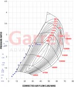
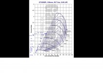
So I've been pretty hell-bent on starting with a supercharger instead of a turbo. We've had success with both (WB Projects with his gt35-based unit; and me with my Vortech (and Vortech knock-off) units. But looking at compressor maps for some of the bigger turbos, it looks like those might be viable starting points as well. What are your thoughts on inducer size vs exducer size vs impeller height for our (relatively low rpm) needs?

I'm wondering if taking like a gt5533 or s488 and milling down the inducer (and putting in a spacer in the volute to make up the difference) would give us more of an ideal compressor?
 
I sure would like to know more and all about it but im just lucky to have make it work the first time. I make my custom back plate for the turbo with 0.015" play between the impeller and the housing but that was a big guess because I had no idea how much gap I need between them.
Anyway, something make sens to me and I don't know if this is true. To make it short, for my small engine, it make sens to me to not go really higher than the GT35 because I dont need more air flow but I need more compressed air (to make more power). For example, If we take your vortech and put it in my car. To push the "same amount of air" we need to compress it A LOT! If we try, the compressor will just surge. It happen to me at first at low RPM.

So, what can I do to increase the pressure on my set up. More blade impeller? Smaller exducer? For sure I would like to know!
 
@AlexLTDLX :
With my rudimentary understanding I cannot predict how an existing compressor map gets tweaked as a result of your suggested mechanical modifications. There most likely are "rules of thumb" for that, but we need here a senior with history/experience in tweaking compressor maps of centrifugal units. (turbo or centrifugal sc are tge same)
I all boils down to "how do we want our target compressor map to look like" for our engine.

@WB projects :
despite your wishes being formulated differently you are looking basically for the same. I theory you want the high efficiency area of your unit/map to get tweaked from a limited "smeared spot" to more extended/smeared down to a cover the lower flow areas (lower engine rpms) ...
shux I wish we would have a drawing board ...
But the same outcome: we need a nerd who can estimate the effect of the different mechnical mods on an existing compressor map.
(Not me ... popcorn ready to learn something new, lol)
 
I appreciate the input. I can't wait to get everything up and running in Texas - things will move so much faster, and I can just test all this stuff on my own dyno without having to make a ton of arrangements and driving 100 miles each way. I could just literally keep the car strapped to the dyno for a month at a time and try out all kinds of stuff - compound boost, twin boost, whatever. And I wouldn't have to make it all integral to the car right away.

I did find out that Audi is using a ceramic coating on the volute to minimize the impeller to volute gap on their newer stuff. I've been looking in to Line2Line abradable coatings for my volute. Truth be told, my volute isn't new - it suffered an impeller crash and the guys over at Jon Bond performance cleaned it up and sold it to me at a pretty decent price. I'm not sure what the clearance is - I'll measure it when I take it out to pull the engine to replace the torque converter. I can tell you that the P2 is pretty tight - I can just get a .016" feeler gauge in between the impeller inducer and the volute. I'll be doing everything I can to maximize this thing, since we are drive power limited.

And I do think WB's thinking is correct - I need less boost and more airflow, while he needs more boost and less airflow. If we can just establish those relationships in particular with regards to drive power, we'd be even further ahead.
 
Have you guys looked into xona Rotors people use them in stock turbo drag racing classes were you can’t use a larger turbo. By using them you increase flow on R35 Skyline by 30%over stock. Were the stock turbo can’t hold 20psi to redline. By using just the xona Rotor in the stock turbo’s they had no problem holding 25 psi to redline. With quicker spool times and way more cfm & boost. You can look at the article by DSPORT Magazine we’re they using them in R35 Skyline.


9B84D4AE-AF86-436F-A977-ED57BFAB00A4.jpeg
 
Hey! Alex so far what i understand from the compressormaps, if you need more air flow and lower boost then you need a bigger compressor which will have a lower rpm, and WB needs more rpm to get the compressor “up” in the map to more boost.
I think :)
I still didnt order my turbo for the same reason, im not sure which compressor will perform better.
WB which bearing did you use in your housing?
 
My knowledge of compressor map is little but what I understand is think about the air volume first. Horsepower can be calculate with the amount of air. If you want to push more air (more power), you need to compress the air since the motor have displacement. For a N/A car the air is at 0psi. So if you want twice more air, you need to push 14.7psi (I think) to get twice more air in the same volume.
So you can calculate your motor spec to get the right compressor for your specifique engine with your desire power. Power will depend of the pressure of the air. Pressure of the air will depend of your brushless motor/compressor.
So you need to calculate the other side
But you need to pay attention to the surge and tchoke region.
I had some problems with compressor surge because the compressor is little too big for low car RPM.
If your goal can be achieve with a low RPM and low boost compressor without getying in the tchoke or surge region, that's your compressor.
Hope that help and really hope that all of this is right 🤣 this is my understanding of the things I read online

For my bearings, is a custom one I ordered on a website. I put all my specs and they made me a custom one. Can't remember the website but I think if you type "custom ceramic bearing" on google you will find it. I will check real quick
 
V-5_F-Trim_compressor_map.jpg

@WB projects ... for your small displacement engine you want a centrifugal setup with such/similar map ... note how steep the red surge line is for low CFM (low engine rpm) (and how "flat" the blue choke line is for higher CFM)

I am sure there are similar turbos out there ... but they would need MUCH higher impeller/eMotor rpms to show some efficiency!
 
Last edited:
@WB projects : so you want increased BOOST at low engine rpms without getting into the surge area:

look at the Y Axis ... you want to get a high pressure ratio ... like e.g. 1.8-2 ... then look at the X axis ... you want low engine rpms/(low lb/min or low CFM) ... you want to stay to the right of the surge line ...
Required impeller rpms are an outcome

;)
 
hello!
I'm trying to figure out the same, which compressor wheel could perform better with which E motor on what RPM. I have an audi 1.8t engine with a bigger turbo and vvt for intake advance around 15degree from 1500-4000rpm and of course i lost torque down low, what i want compensate (and i want to try something interesting :) )

I made from my logs 2 compressormaps where i am on the map to see which will be better.
The whole thing is more tricky because my engine is already have a turbo it just cant build boost down low ( it is making some but not much), thats what i want to help,
with an E-Turbo what doesnt make any backpressure just flow more air through the engine will help a lot the turbo to spool up.

I made from my logs a gt35 and a gt45 compressormap (see below), they are both on the left side of the surge line IF i use as a turbo, but how is it look like as an e turbo? It can push some more airflow soo it will more to the right on the map right?!
The engine can flow more with a smaller turbo so the engine should not choke the e-turbo.

On a gt35 im right on the surge line, on a gt45 im a little far too the left of the surge, BUT a gt35 moving some air after 50k rpm, and a gt45 is already after 33k rpm which is easier too reach with a brushless motor.
What is the compressor doing under those rpm lines, soo under 50k rpm and under 33k rpm?

Did someone already tried how the brushless motors hold an overvoltage? i mean if i build this whole thing with an 8S motor, then use with a 9S or 10S battery?
 

Attachments

  • gt35.jpg
    gt35.jpg
    661.1 KB · Views: 1
  • gt45.jpg
    gt45.jpg
    276 KB · Views: 1
I've tried over-volting brushless motors. Turns out brushless motors don't work out the way I thought they would - it's more about duty cycle and then staying out of saturation. Pushing more volts can actually lower duty cycle which leads to similar overall power in the system. That's what I found with the VESC tests I was doing. Take my previous TP Power setup - I was over volting that thing substantially, and all that happened is duty cycle went down.

However, that doesn't mean that there aren't other things to explore (which is why I want to spend more time with the VESC and this 4 pole Castle motor I bought). Before I wanted to put something on the car that was a step up from what we've had before. The Sledgehammer has done that. Now I want to play with things like motor timing in trapezoidal control, and maybe some other tweaks in FOC control. Honestly, I'm not sold on FOC control as the ticket to max motor power. But it's entirely possible I'm wrong.

As for a compressor, I'd try the GT45. We know that WB's GT35 works, but what we don't know is the compressor/rpm relationship yet. From a selfish perspective, I'd love to know if the GT45 works better than the GT35 does.
 
The vortec look good
yes ... the V-5 (above vortech map is for V-5 F trim) seems to be exactly what you need for smaller displacement engines (1.5-4.0 l ) !

looky what I found 😁 :


and here some "parts for the mad scientists" amongst us:
(you might want to ask the seller about tge impeller trims though ;)
 
I've tried over-volting brushless motors. Turns out brushless motors don't work out the way I thought they would - it's more about duty cycle and then staying out of saturation. Pushing more volts can actually lower duty cycle which leads to similar overall power in the system. That's what I found with the VESC tests I was doing. Take my previous TP Power setup - I was over volting that thing substantially, and all that happened is duty cycle went down.

However, that doesn't mean that there aren't other things to explore (which is why I want to spend more time with the VESC and this 4 pole Castle motor I bought). Before I wanted to put something on the car that was a step up from what we've had before. The Sledgehammer has done that. Now I want to play with things like motor timing in trapezoidal control, and maybe some other tweaks in FOC control. Honestly, I'm not sold on FOC control as the ticket to max motor power. But it's entirely possible I'm wrong.

As for a compressor, I'd try the GT45. We know that WB's GT35 works, but what we don't know is the compressor/rpm relationship yet. From a selfish perspective, I'd love to know if the GT45 works better than the GT35 does.

hey!
Sooo i ordered a gt45, i give it a try then we will see if it is better or worse :)
I have an aftermarket ecu so i will se exactly how good is working.
I am planning to control the vesc with my ecu.
I went for a tppower 4060cm 8S, and will try it with 10S battery.
I ordered the flipsky 200/300A vesc, i read on some forums about the flipsky and it is not bad, some guys pushing it pretty hard with Amps :)
The config of vesc will be tricky, but its okay :)
About the compressorhousing, and turbo, did you guys use the shaft from turbo or is it self made?
The shaft from e motor is flatened so there could be fixed with some screws and loctite, i dont want to throw a compressorwheel in my engine :)
Wb Project already told and sent a link with the ceramic bearings what he used it will be good for me too i think.
If you guys have some really important info about this what i must to look and make, please tell :)
Thank you
Let’s build one more e turbo :)
 
I use a custom shaft that I made and glued it with green loctite. The worst to make is this. You want it to be perfectly concentrique. I was able to make it almost perfect with 0.0005" with all the critical diameter of the bearing and impeller seats after my 5th try with almost 1hour each 🤣 anyway there's some way you can get away with some tolerences.
You can check an other time my old video where I show how I build it. If you have more space, you can change de design to compensate the allignement adding a bearing etc.
 
hello! i made a quick draw in cad (yes im a beginner :)) for the shaft of the turbo, what do you think about this design?
I'm thinking where the shaft of the motor is flattened to fix it with two screws and loctite?
the shaft from the e motor is 5mm, and its 13mm long flattened, im not sure how thick should be this shaft where the e motor shaft came inside.


tengely.jpg
 
Top