Initial build of Twincharger

Couple of notes. My backplate is very thick and printed with 100% infill. (Why would you do anything else?) You must restrict the decel (and to a lesser degree the accel) of the esc in the code to limit instantaneous current and inertial forces on the rotating assembly. How are you measuring the current? The thread and nut are pretty important as well. You shouldn't keep retorquing the joint as the threads will wear and loose clamping force.
Also carbon-nylon is much stiffer than ABS so with the 100% infill density and material there deflection should be considerably less.
 
Last edited:
Couple of notes. My backplate is very thick and printed with 100% infill. (Why would you do anything else?) You must restrict the decel (and to a lesser degree the accel) of the esc in the code to limit instantaneous current and inertial forces on the rotating assembly. How are you measuring the current? The thread and nut are pretty important as well. You shouldn't keep retorquing the joint as the threads will wear and loose clamping force.
Also carbon-nylon is much stiffer than ABS so with the 100% infill density and material there deflection should be considerably less.
I paid the extra money bought the blue tooth adaptor for the Hobbywing max4 ESC. I am using the built in data logging function on the ESC. I configured it for a 4 pole motor. So I can see amps, voltage, RPM, temp as a function of time in the run and map out the correlation. Pretty slick. Just wish the motor temp and PSI were there. D45FE838-BB26-4819-8E12-1756657C808A.jpeg
 
Good question. There seems to be very little end float. I think it is mostly a combination of the nut loosening due to fast deceleration and flex in the back plate. I am still waiting on my laser sintered stainless shaft and hopefully they works for me. Here is the update. I will start a build page for my project as it is looking promising.

Well, my goal this weekend was to make some sort of boost in the basement And….At the last minute, goal achieved!
Motor vehicle Wheel Art Font Graffiti


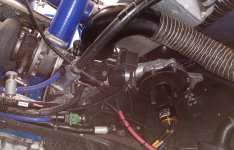
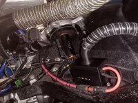
I was basically struggling to overcome the instability of 3D printed parts flexing under load and the compressor nut loosening causing interference between the compressor and volute housing.I greatly increased the rigidity of the backplate by probably 5-10X. I started using a cubic infill (vs zig zag) at 70% (up from 20% infill) and slowed down my printer to 70 mm/sec to get better layer to layer adhesion with my ABS filament. Once the design stops changing, I will eventually make an aluminum back plate. Problem solved.

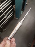
Then I got out the dial caliper and made some adjustments to get the extension shaft run out below about 5 thousandths of an inch. This is the best I can do with the coupler approach as an interim solution as I wait for my laser sintered stainless extension shaft.

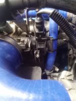
One problem that I had was the electronic brake. The compressor wheel was slowing down too fast and the nut would come loose and the compressor wheel would lift off and touch the volute housing. I am tuning the brake settings and letting it coast a bit more and ordered a 10 mm x 12 point socket so that o can tighten the left hand thread nut in place without taking apart the assembly each time. I had initially applied the brake settings as a safety mechanism, but turns out that it might just make things more dangerous. For the final assembly I will probably use loctite, but right now it gets tore down and put back together several times a day.

Earlier in the week, I had only spun it up to about 0.1 PSI before things would get wonky. I didn’t even think the amp meter was working on the Electronic Speed Control data logger.

But with a more concentric and stable set up, I then spun it up to about 0.4 PSI, the 1 PSI today and was rejoicing. Then got bolder and wound it up to 1.5 PSI. Then I went for 2 PSI. I can’t remember where I finished but it was north of 2 PSI. I don’t know if I will get much beyond this without the new shaft which hopefully gets runout of less than 1-2 thousandths.

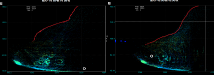
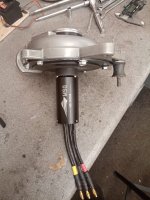
Below is the data log from the last pull of the day. At the 3rd peak is where we hit somewhere in the order of 2.2-2.4 PSI. I was so excited to be able to make boost! From here it is a matter of refinement, continuous improvementand optimization.
Rectangle Slope Plot Font Parallel


Here are some key observations I make when looking at this data.
  1. Lots of Data: I love having the data handy so that I can see what is going on and tune the system. That said the downside is that I am missing some data, like motor temperature and PSI as they are on different measuring devices. I was for instance happy to see that the ESC accurately tracked voltage and amps real time, so I could put my multimeter and amp probe away and focus my eyes elsewhere.
  2. Right Voltage: I decided to go with a higher voltage battery than the motor says it can handle. This is what I think WB said he was doing and confirmed by Castle. I built a 12 LiFePO4 cell x 3.25 volt battery = 39 volts nominal. This is where the purple line starts. But under load you can see it drops to 33 volts. Interestingly, the Castle 1721 says it can handle a maximum of 33.6 volts. I still need to get a proper charger as I am charger half the bank at a time.
  3. Digital RPM. I simply changed the setting in the app on my iPhone and configured the ESC for 4 pole motor. The digital readout on APP is then actual RPMs of the compressor wheel, since it is direct drive. The highest the RPM for was about 45,000. This motor is rated to 90,000 (which is where the rotor flies apart). I need to put a safeguard in to stay well below that number with a safety margin. That said, more RPMs = more boost!
  4. Amps: I thought that my ESC was not working right, but it turns out that it can’t really measure anything when idling along at just a few thousand RPMs. I was slowly getting more aggressive. On this last run at over 2 PSI, I hit over 71 amps (red line). Throttle (blue line) was at 39% and RPMs were an out 45,000. So, there is still some headroom and hope to get to the targeted 5-7 PSI boost.
  5. Heat. I have heard of lots of ESCs (electronic speed controller) blowing up and catching fire. So I spent extra money here and bought the biggest one I could afford (high end of the low end). It is a if chunk of meter with a lot of built in cooling and no surprise. It runs cool. It did not quite get up to body temperature. The motor. That was a different story. It got hot.
6 volts of drop from the battery to the ESC is very high. For 3 feet of 8 gauge it should be less than 1 volt for 71 amps.

Also recognize that because the ESC is throttling (reducing the phase voltage to control speed) the phase amperage to the motor is considerably higher than 71 amps. 33.2 volts times 71 amps is about 2.4 kW. So if the phase voltage is cut in half the phase amperage doubles to still have 2.4 kW.
 
Last edited:
Finished bench testing my phase 2 motor, a MSQ2600KV which should give me around 68krpm instead of 59krpm of my original motor. The original Rocket 4074 has so far proved ultra reliable and the whole system has worked pretty seamlessly in the car with some additional mapping to richen up the areas of the map that was never achieved before. The only additional thing I did was crack open the bypass slightly at very low speed to move away from the surge line. The bypass is open at all times when the supercharger is inoperative to eliminate the pressure drop across it.
The opening rate of the motor has been reduced to around 0.15s and the closing balanced to equalise the peak current.
Lag has all but disappeared but you still notice a second step in torque as the main turbo picks up. The graph shows with/without the supercharger. Hopefully the new motor will give me another 0.1bar or so. Very happy with the results so far.
I have a phase 3 TP SCM motor in the background as well which should give 100krpm but I will need to modify the rotor to minimise wheel overhang - I am hoping to only use the top bearing in the motor for support.
 

Attachments

  • no motor boost comparison.png
    no motor boost comparison.png
    104.6 KB · Views: 12
  • IMG_20230622_214833.jpg
    IMG_20230622_214833.jpg
    452.7 KB · Views: 12
Last edited:
Would you be able to share what you are using for the bypass? I need to start planning for getting my system on the car and have been pondering this point. Do you control it also with your ECU or are you using another sort of micro controller? Also, are you triggering just based on throttle position sensor?
 
Yes here is a shot of the system. This one has a BOV take off which has since been deleted. It is just a throttle body coupled to a servo driven from the arduino that controls the ESC. I found it easier than a drive by wire throttle body as I struggled to control it with an external H bridge.
The valve is controlled by boost/throttle position and engine speed. Hence I can avoid low speed surge with an appropriate position of the valve. This will be more important with the larger motor.
The valve is only partially open when the supercharger is not in use as it takes less time to close and is also effectively unrestrictive since the throttle valve diameter is relatively large.
Care has to be taken so that the valve seals well when requested otherwise you will obviously loose boost pressure.
 

Attachments

  • IMG_20230531_082428.jpg
    IMG_20230531_082428.jpg
    428.1 KB · Views: 15
Last edited:
Final spec of motor has now passed bench tests and in the car awaiting mapping. The motor is a TP4070SCM 3930KV so capable of around 100krpm. Since the speed is so high I decided to modify the rotor and shrink the extension shaft onto it and use that as the top motor bearing surface (obviously a larger bearing I/D was required) . Hence the overhang is minimised and no spacer is required although new end float control spacers were needed. I also had a go at making the shaft myself and it took a few attempts to get the machining methodology correct for acceptable runout. Pretty sure more development will be required but OK so far.
 

Attachments

  • IMG_20230711_083717.jpg
    IMG_20230711_083717.jpg
    171.2 KB · Views: 27
  • IMG_20230709_173516.jpg
    IMG_20230709_173516.jpg
    143.9 KB · Views: 24
Now fitted and working as it should. Generates around 0.7bar boost before the turbo kicks in and pretty happy with the result. Absolutely no lag, instant response and still about 10krpm to go. I did fit a fan assisted heat sink (another on order) to keep the motor body temp under control as I did notice it started to get hot on the bench tests, however that was running a greater duty cycle than in the car. I would now say job done.
 

Attachments

  • IMG_20230716_110538_s.jpg
    IMG_20230716_110538_s.jpg
    407.5 KB · Views: 14
Last edited:
Final spec of motor has now passed bench tests and in the car awaiting mapping. The motor is a TP4070SCM 3930KV so capable of around 100krpm. Since the speed is so high I decided to modify the rotor and shrink the extension shaft onto it and use that as the top motor bearing surface (obviously a larger bearing I/D was required) . Hence the overhang is minimised and no spacer is required although new end float control spacers were needed. I also had a go at making the shaft myself and it took a few attempts to get the machining methodology correct for acceptable runout. Pretty sure more development will be required but OK so far.
Wow, I really like what you did with the shaft. I am still trying to get my head around what you did. I like eliminating the spacer. How low did you get the run out? I already have a functional system, but have kept the RPM for now around 60,000 which is about 6 PSI. So, what did you do to control the end float with your new approach?
 
Last edited:
Wow, I really like what you did with the shaft. I am still trying to get my head around what you did. I like eliminating the spacer (mine is now down to 8 mm). How low did you get the run out? I already have a functional system, but have kept the RPM for now around 60,000 which is about 6 PSI. So, what did you do to control the end float with your new approach?
Run out is about 0.0004" which I think is good enough (obviously is). The end float control is just the same as the original motor i.e a bronze bush. It is just a different o/d and i/d with the correct thickness to get the end float. Also in detail there is a different sizes shim to prevent contact of the bush on the aluminium casing of the rotor
 
One final modification I have just made for the twincharged installation is an uprated ESC. My original one was close to max for the TP motor and sooner or later I suspect it would have had an issue. So I have installed a Hobbywing Max series ESC which can handle a very high instantaneous current and thus I can push the motor to its max speed at a high acceleration rate. In doing so I realised that the neutral point was half way between min and max (obviously) but since the arduino code drives the ESC as a servo it starts at 0 rather than its neutral point. Therefore I was wasting half the opening period just waiting to get to the neutral point before the motor even begins to accelerate. Hence with a bit of help from ChatGPT (to make the most efficient code) I have made a two stage opening rate, initially to the neutral point very quickly, then starting the motor at a rate I was comfortable with to keep the instantaneous current at an acceptable level (the closing rate has been kept the same as it makes no real difference)
Now when triggered, the motor accelerates to max speed in less than 100ms. This is faster than it took the bypass valve to shut so the speed of this was increased by increasing the supply voltage to the valve's servo. Now the valve shuts at about the same rate as the motor takes to get to max speed.
In the car it feels virtually instant as the supercharger is engaged.
Bar any reliability issues I think that is it, no more fiddling! The system seems seamless in operation. Pretty satisfied with the overall result.
Below is the installation of the new ESC. Wiring a bit messy but it is a prototype!
 

Attachments

  • IMG_20230901_203403.jpg
    IMG_20230901_203403.jpg
    540.5 KB · Views: 15
Last edited:
I had the first issue with the system. Unfortunately my ECU does not support CAN so I used a second TPS and initially fitted a non automotive potentiometer as the throttle input. I thought I might get away with it but vibration and heat killed it. So a quick redesign with a conventional TPS and we are back up and running fine. Performance is so good and using the supercharger is intoxicating!
 

Attachments

  • IMG_20231116_094805.jpg
    IMG_20231116_094805.jpg
    326.8 KB · Views: 11
Last edited:
Final spec of motor has now passed bench tests and in the car awaiting mapping. The motor is a TP4070SCM 3930KV so capable of around 100krpm. Since the speed is so high I decided to modify the rotor and shrink the extension shaft onto it and use that as the top motor bearing surface (obviously a larger bearing I/D was required) . Hence the overhang is minimised and no spacer is required although new end float control spacers were needed. I also had a go at making the shaft myself and it took a few attempts to get the machining methodology correct for acceptable runout. Pretty sure more development will be required but OK so far.
Thank you for sharing. I am still trying to get my head around your design which is so simple yet robust in the right ways.
  1. So, how is the motor mounted to the turbo housing? I am guessing 4 machine screws with the compression limiters since 3D printed housing.
  2. Did you machine the original motor end cap for the larger bearing? And larger opening for the extension shaft OD? Do you happen to have before and after pictures?
  3. How big did you go on the bearing? I am guessing the ID is 1/4” + 2 x wall thickness. The OD on my recent shafts was near 5/8”
 
1. Correct
2. End cap is original
3. Bearing is same o/d and width just larger I/d to match the larger o/d of the extension shaft
 
1. Correct
2. End cap is original
3. Bearing is same o/d and width just larger I/d to match the larger o/d of the extension shaft
regarding point 3 above, the bearings on my castle 1721 are tiny and their walls are super thin. I think that the OD of the bearing is smaller than diameter od the extension shaft. Hence I wonder if it would work to eliminate the original motor end cap in the spirit of shortening the shaft. In this case the impeller housing backplate would be attached directly to the motor housing with screws.
 
I think you may need to make a new end cap in this instance, otherwise you would probably have to line bore the motor housing and backplate whereas you could make the bearing bore concentric with the spigot diameter on the new end cap
 
Out of curiosity, what is the wall thickness of your extension shaft?
IMG_2447.jpeg
Mine is about 3.8 mm. I am wondering if I have excessive force due to the wall thickness and what a lower viable limit may be.
 
It is 1mm. The force is proportional to the amount of interference. If the diametral interference is 10microns or less you should be fine
 
It is 1mm. The force is proportional to the amount of interference. If the diametral interference is 10microns or less you should be fine
Hmmm my interference may be a bit too high as well. It is hard to measure the inner diameter of the hole in the extension shaft. But theoretically I am actually at about 17 microns of inference. Now that I have my technique down, I may try my 0.3140” reamer rather than the 0.3135” reamer that I have been using. That should decrease my theoretical interference to about 4 microns. That may solve my warping problem if it is enough inference
Final spec of motor has now passed bench tests and in the car awaiting mapping. The motor is a TP4070SCM 3930KV so capable of around 100krpm. Since the speed is so high I decided to modify the rotor and shrink the extension shaft onto it
the only way I can figure to get rid of the spacer is to shorten the motor rotor drive shaft. Did you essentially trim off the part of the motor shaft that stuck out of the housing and mate up the extension shaft in the motor housing?
 
Top