Initial build of Twincharger

matnrach

Member
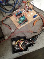
First stage is completed of my twincharger. This will only be used upto around 2700rpm before the main turbo spools properly. The engine is a small displacement 4cyl so the power required is low as I only require about 0.25bar.
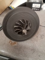
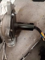
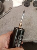
The motor is a 4074 running @ 24V. Compressor is off a GT2056 .
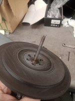
I chose to use a 3D printed backplate (Nylon with 25% carbon fibre) with a PEEK front bearing with 50mics radial clearance. It is bolted to the motor with steel compression limiters.
The motor extension shaft is interference fit only with 20microns as this should be sufficient.
So far it has worked faultlessly and does produce around 0.25bar at the required flow.
Next is to fit to the car, get it running and sort the throttle position/speed to engage and disengage the supercharger.
We will have to see if a bypass is required or maybe just increase the boost slightly to compensate for the inlet depression from the supercharger.
 

Attachments

  • IMG_20230121_101157.jpg
    IMG_20230121_101157.jpg
    865.3 KB · Views: 26
  • IMG_20230121_101117 (1).jpg
    IMG_20230121_101117 (1).jpg
    774.6 KB · Views: 28
  • IMG_20230121_135314 (1).jpg
    IMG_20230121_135314 (1).jpg
    760.5 KB · Views: 26
  • IMG_20230121_101247.jpg
    IMG_20230121_101247.jpg
    671.8 KB · Views: 26
Project coming along now. Decided to get a much larger motor , a TP4070SCM capable of 100000rpm and hopefully 0.5-06bar boost at low speed before the main turbo kicks in. ECU made with an Arduino UNO using throttle position, boost and RPM to control the compressor and bypass valve. Code mostly written by ChatGPT which worked very well. Here is a picture of a HIL (Hardware In the Loop) rig with a signal generator simulating the tacho output from the Engine control unit and the actual ECU for the vehicle. Hopefully up and running in a few weeks.
 

Attachments

  • IMG_20230312_103723.jpg
    IMG_20230312_103723.jpg
    532.9 KB · Views: 19
Wait - what? Code written by ChatGPT? More information, please - software is my weak spot...
 
Yes, most of it was written by ChatGPT but you have to be very precise in what you ask it. It can only do so many characters as well so you really need to only ask it to do sections of code. It is like anything really, you need to invest time to get the most out of it.
 
No not sure why I would want to do that. If you want to have a go start with a simple program but to be honest you need to have a basic idea of the programming language before you start. I would say it is similar to doing anything new, it is a steep learning curve and you need to invest time.
 
The motor extension shaft is interference fit only with 20microns as this should be sufficient.
Pretty cool. I am going down a similar path. Did you just cut off the original turbo shaft? I just took my turbo about last night to get the isolated compressor housing and shaft. It looks like the shaft is about 0.25'. How did you attach the motor extension shaft? Did you heat it up and then slip it on the motor shaft? In one of your pics it almost looks like it has been welded. I like the simplicity of the approach.
 
Pretty cool. I am going down a similar path. Did you just cut off the original turbo shaft? I just took my turbo about last night to get the isolated compressor housing and shaft. It looks like the shaft is about 0.25'. How did you attach the motor extension shaft? Did you heat it up and then slip it on the motor shaft? In one of your pics it almost looks like it has been welded. I like the simplicity of the approach.
It is an interference fit on the motor shaft. As I stated initially it has a 20micron interference, so had to be heated up to around 450-500 degrees to slip on. The shaft has to be pretty accurately made though.
 
The required interference fit to hold 15 Kw at 50000 rpm is not real big. 20 microns (0.000787") is plenty. Tolerance range is something like +/- 0.0005". Too little interence and couplng will slip. Too much and won't be able to assemble just by heating the sleeve. Need a lathe with digital read-out or CNC control to bore the hole.
 
Having a digital readout is certainly not enough. You need an extreme amount of machining skill and the correct metrology to do it. I have a small machine shop at home but for this job I enlisted a very experienced friend with the latest machines to do it. In fact he thread milled the LH M5 thread and I dont think we could actually measure any runout (which is probably the most important aspect as it spins at 100000rpm). Also the concentricity of the bore to the shaft must be within a few microns.
 
Last edited:
It is an interference fit on the motor shaft. As I stated initially it has a 20micron interference, so had to be heated up to around 450-500 degrees to slip on. The shaft has to be pretty accurately made though.
Got it, I like the approach. At first I thought it was sort of a coupler that connected the sawed off compressed shaft and the motor. From what I understand now, you actually made a new shaft threads and all. I did not know for sure that interference shafts are heated up, just guessing because of the color. That totally makes sense and I will head in that direction. Just learning as I go.
 
Got it, I like the approach. At first I thought it was sort of a coupler that connected the sawed off compressed shaft and the motor. From what I understand now, you actually made a new shaft threads and all. I did not know for sure that interference shafts are heated up, just guessing because of the color. That totally makes sense and I will head in that direction. Just learning as I go.
A word of warning though. The shaft MUST be extremely accurately manufactured or you risk vibration and ultimately a mechanical failure
 
Got it, I like the approach. At first I thought it was sort of a coupler that connected the sawed off compressed shaft and the motor. From what I understand now, you actually made a new shaft threads and all. I did not know for sure that interference shafts are heated up, just guessing because of the color. That totally makes sense and I will head in that direction. Just learning as I go.
Having a digital readout is certainly not enough. You need an extreme amount of machining skill and the correct metrology to do it. I have a small machine shop at home but for this job I enlisted a very experienced friend with the latest machines to do it. In fact he thread milled the LH M5 thread and I dont think we could actually measure any runout (which is probably the mos t important aspect as it spins at 100000rpm). Also the concentricity of the bore to the shaft must be within a few microns.

From the pictures it looks like there is a sleeve on the motor shaft and then a threaded extension shaft in the sleeve. If there is a sleeve, is the attachment to the motor shaft interference or set screw?
 
It is an interference fit extension shaft with an integral thread. There is no sleeve. So the concentricity, straightness, runout etc must be made to an extremely high accuracy for it to work properly. As I said, luckily I have a friend who is a better machinist than me who has the latest machine tools and measuring equipment available.
 
I have now fitted the complete system to the car and after some engine and arduino code mapping it works very well even with the small motor. The TP4070SCM will be fitted shortly so this should be a big improvement. I may have to upgrade my ESC as it looks like I need to drive the motor pretty aggressively for best response. At the moment my ESC can handle upto 920A burst current but that is on paper!
 
It is an interference fit extension shaft with an integral thread. There is no sleeve. So the concentricity, straightness, runout etc must be made to an extremely high accuracy for it to work properly. As I said, luckily I have a friend who is a better machinist than me who has the latest machine tools and measuring equipment available.
So the extension shaft is dual diameter? The large diameter section was bored to make an interference fit over the motor shaft?
 
I am interested in this approach. I looked at Garrett T04E clones on-line and they are dirt cheap. They are a nice fit for my 2.8L V-6 pushrod project. Was the final sizing of the bore done with a boring bar or an adjustable reamer?
 
The required interference fit to hold 15 Kw at 50000 rpm is not real big. 20 microns (0.000787") is plenty. Tolerance range is something like +/- 0.0005". Too little interence and couplng will slip. Too much and won't be able to assemble just by heating the sleeve. Need a lathe with digital read-out or CNC control to bore the hole.
I did my first one with 0.002“ too loose. I put loctite and it did well. The second one I try the shrink fit but I mess up..https://youtu.be/t5XNN7z8_lQ
 
I’ve made mine pretty similar and I have tried different thing and it is impossible to get a perfect concentrique shaft without a grinder.. a bearing is needed to support the shaft
 
Top