How does a 2 pole LMT motor work?

AlexLTDLX

Administrator
Staff member
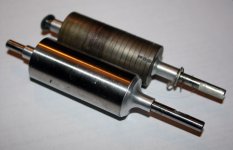
Since I'm getting frustrated with the VESC/P2 setup (the P2 part works fine; the VESC is giving me a lot of issues), I'm turning my attentions to the Sledgehammer MGM/LMT setup. My 30100 LMT motor is a 2 pole deal with 6 connections on the back. It spins easily by hand (unlike the TP Power motor); I did take one youtube poster's advice and tried shorting a couple of phases and then turning it - and it suddenly was hard to turn.

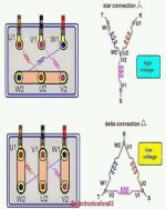
How do these work? Anyone have a schematic for them? I don't understand the 6 connection thing, and the instructions for connecting seem very arbitrary - with this much power (both battery and ESC/Motor), I really want to understand what I'm doing. Any input is appreciated.
 
At a guess you connect them in series to 1/2 the KV or in parallel ... The advantage in parallel is you can use more "wires" to the motor to 1/2 the resistance of the wires going to the motor... That's my guess.. i have no idea how to wire them up
 
Looks like LMT motors with 6 connectors are wound in a nice (open!) way which actually allows you to configure the winding termination as you need.

see here the explanation regarding 6 connector 3 phase motors:

The straps I am referring to in above post are called Delta Straps (read the link above) ... but actually only do the same on motor side what has always been done on MGM ESC side! (so you can simply use 3 wires to any esc ... and run the motor in Delta winding configuration!)

Btw ... LMT rpm rating is said to always have been specified under load ... (vs free spinning ... how much load is unclear though)
 
Last edited:
Thanks for the input, guys. What's really confusing to me is why you can choose any connector at random on the back of the motor. I've seen that video before, but it's handy to have it here. I would love a schematic of the motor, and I would also love to understand why the motor spins freely unless you short out some of the connections on the back. Like nature abhors a vacuum, I abhor not knowing how something works.

Tomas at MGM did tell me I could use straps, but thanks for clearing up the delta thing (that that's what MGM ESCs basically do on the ESC side). He did say it was better to run 6 cables though. Which is why I bought 150 feet of 4 gauge cable (overkill? maybe, but it's better than underkill and having more problems).
 
It does not matter which connector you start with because they are all identical . They are just coils of wires so it doesn't matter which one you choose first.

As for resistance to rotation. The resistance to rotation is caused by magnetic forces interacting between the coils on the outside and the magnets on the inside.. Obviously the inner magnet is permanent so that is always creating a force..

I believe that when you manually turn the motor it that causes current/ voltage in the windings, then when connected together it allows the current to flow somewhere, which then creates a magnetic force that counters the direction of rotation ( you turning it ).

Interestingly you can take a stepper motor from a 3d printer and you can turn it relatively easily.. However if you take the 4 wires and twist them together is it difficult to turn...

The same is true if you take your TP motor with just 3 wires coming out of it .. If you connect them all up and try to turn it it will be harder to turn than them not all connected up to each other.

As for an alternator it has two coils and no permeant magnets. This is cheaper to make and does not have the potential service problems of endlessly colleting iron.. With the outer coils connected up it also has no resistance to spinning, But also can't generate any power... As power is then applied to the inner coils magnetic force is increased and thus more power can be produced... IT's actually pretty cool cos you can adjust the output power of the alternator buy adjusting the power to this coil.. but also this puts a variable load on the engine too. More load when you need the power and less when you dont.
 
It sounds like a typical three phase motor having 6 connections.

These are usually wound with 3 or more electromagnets

Usually you need to link different cables together depending on if you want star or delta


Easy way to tell is, it should be 3 pairs.

For delta link 1 cable from each pairs then put power to the other side of the pairs
 

Attachments

  • 1646672275781.png
    1646672275781.png
    63.3 KB · Views: 5
MSA - So why is the TP Power motor difficult to turn and seems to cog between poles? And the LMT motor is smooth and easy to turn unless I short out the windings, and then it becomes harder to turn but doesn't cog - it still turns smooth?

shanky - That's kind of what I'm thinking, but I'm still having a hard time picturing how it would work if you randomly chose a start point on the motor as they tell you to do. Wouldn't it be possible to send the same leg of the ESC output to both sides of a phase resulting in no power?

I guess I just need to measure it for myself.
 
I just went ahead and measured it. It's 6 connectors in a circle. Turns out, opposite connectors are a coil. So if one connector is at 12 o'clock, the other side of the coil is at 6 o'clock. Same with 3 and 9 o'clock, etc. FWIW, each coil measures ~3.1 milliohms. I suppose that's why it's possible to connect at random and not short anything out, as long as you go in order.

But I'm still not grasping why it doesn't cog like the TP Power motor does. Unless that has to do with not shorting out the right connections?
 
Both motors are 3 phase motors.. The TP motor like most Motors have those connections wired up internally ..
The LMT does not.. The LMT is meant to have them shorted just like the TP motor but instead of doing that inside the motor they let you do it externally at the ESC .. This is a good idea as you now have twice as many wires delivering the current to the motor.

They can be seen shorted together here.

1646721119872.png

Shorting the pairs will make it harder to turn and then shorting all 6 together will make it even harder. ( obviously with all 6 it can't run like that but you can try it without danger ).

It's not fair to compare the LMT motor to the other motor when these are not shorted together Because they will ALWAYS be shorted together.

If you're comparing the LMT shorted in pairs to the TP and expecting them to feel the same, I certainly wouldn't expect them to feel the same as they are completely different motors. One being being 2 poles ( i think you said) and the TP being 6 poles..

Even if they were "the same" that doesn't mean they will feel the same. I literally have a box full of 14 pole 2205 motors. I would have expected them to feel the same when rotated by hand but some feel wildly different to each other.. Some are extremely coggy and others rather smooth. I was expecting the smooth motors be be rubbish on my Brushless motor dyno, but in fact it didn't really mater.
 
This might be helpful

1646725341848.png
1646725370559.png

Connected in D or Y 1/2 of the wires are connected together.

it would actually be interesting if you changed it between D and Y if that has any affect on cogging.. i assume it would..
 
Here is the same tp motor some wired in D and some in Y.
I would have thought your motor would have had 2 ratings one for D and one for Y .. but instead they have no ratings at all ( well free KV )

I guess we could then continue this discussion with the benefits and drawbacks of D and Y.. I wont though .lol


1646725771068.png
 
Yeah, I'm ok on the differences between wye and delta configurations. I'm also starting to wrap my head around this LMT motor. I do wish their website was a bit more in line with other manufacturers in how they list specifications - I think they would see more sales, frankly.

On the bright side, every day I'm making a little more progress on the sledgehammer. In fact, the motor now mounts to the plate (with 2 bolts; need to do 4 more) and I just need to measure/cut down the hex drive socket and drill and tap a setscrew hole. The rest of it already machined. I could probably start testing shortly thereafter, and hopefully it's much less dicking around than the VESC/P2 setup. The sad thing about the P2 setup is it works mechanically just fine. It's the electrical stuff that's the issue.
 
Something I just ran across, the LMT inrunner motors are slotless. That means the only iron in the motor is the outer housing (simply to complete the magnetic circuit), there are no teeth for the magnets to attract to, so you wont feel any cogging from the magents when spinning the motor by hand. This also means that you likely can’t saturate the LMT motors with too much current.
 
I was told that you don't feel cogging when fewer poles - so my TP Power motors cog pretty hard (6 pole); my Castle motor cogs a little (you can feel it, but it doesn't really make it difficult to turn - it has 4 poles); my 2 pole LMT motor spins smoothly.

I'd love to see some sort of diagram of the inside of the LMT motors to have a better understanding of what's going on inside.

Here is a description of the differences:
https://www.haydonkerkpittman.com/l...aring-slotted-vs-slotless-brushless-dc-motors
 
It took forever, but finally found some actual pics of the inside of a Lehner inrunner motor. This is the slightly smaller brother, a 22 series. As you can see, no teeth, no cogging! The rotor with the multiple rings is the Lehner rotor. Apparently they assemble it, then magentize it.

22 series stator.jpeg
 

Attachments

  • 22 series rotor.jpg
    22 series rotor.jpg
    47.3 KB · Views: 6
Top