Hi all - I've started making some progress on my build and all the information here has helped a lot so i thought i'd post up what i have.
I'm using the P2 supercharger as it requires lower RPM which I though would be easier to manage.
When delivered i found the bearings a little noisey and as noted here are only rated to 22,000 RPM.
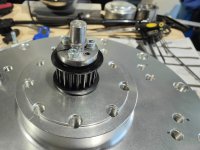
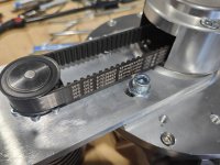
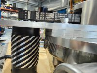
I've since remade the shaft from precision ground 10mm round bar. I've changed to HTD 5M15 pulleys to allow some testing with different ratio's
The HTD belts are rated around 80m/s i think and were suitable for the desired motor RPM. It should also be slightly more efficient / generate less heat than the original T5 solution.
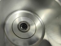
I made a taper lock to fix the pulley to the shaft and its working quite well. I made bushings to suit new bearings. I chose 6800ZZ that are rated to 38,000 rpm and everything rotates much more smoothly now. The bearings have a lower dynamic load rating than the original but i haven't noticed any issues so far. I have room to double stack them if needed.
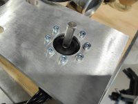
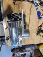
I've mounted the motor "upside down" to try and reduce the package height of the whole assembly. I've used 2 x 6mm sections and 1 x 10mm section of aluminium flatbar to space the motor up for belt alignment. The motor is recessed into the top plate 4mm.
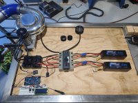
I'm currently using 2 zee 6s 9000mah packs for testing but seeing more voltage droop at high power than I'd like. I still need to go over connections and clean up anything there but I think i need another 2 packs to reduce the load per pack. This runs through a 3 phase isolator I picked out of the scrap.
I'm using an arduino board to control the ESC because I eventualy want to tap the CANBUS in the car to drive it. I'd like to use shaft speed to set targets but unsure how i'll manage this. Might be able to get motor speed from the esc and use that?
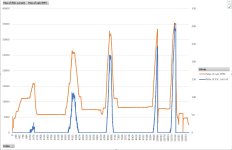
I've got the hobbywing OTA adapter for the MAX4 and successfully pulled the logs to the desktop. I've worked out what all the data is except 2 additional values not shown in the app. Just need to figure out how to script the conversion to csv. I'm learning as I go though and enjoying it.
Next steps
Eliminate as much voltage drop as possible.
Investigate further battery options
Testing current draw at different drive ratios to see what the motor prefers - I have 20t on the shaft and 24, 28 and 32 available for the motor.
Housing for the belt drive.
Maybe some flow testing to benchmark to the vortech map. I've thought about using a cheap MAF for this othwise i'll go down the now standard restrictor method.
The peak motor RPM below was 35,300 so 42,360 impeller RPM at 10,584watts. The current spike on ramp up was 308.2A / 11,126W. It was very much a hide behind something and see whats going to fail moment.


